
Automatic material collecting device for punch press production line

A collection device and production line technology, applied in storage devices, feeding devices, positioning devices, etc., can solve problems such as unfavorable health

Active Publication Date: 2021-02-09
UNIV FOR SCI & TECH ZHENGZHOU
View PDF30 Cites 0 Cited by
  • Summary
  • Abstract
  • Description
  • Claims
  • Application Information

AI Technical Summary

Problems solved by technology

The punch press applies pressure to the material to make it plastically deformed to obtain the required shape and precision. Therefore, a set of molds (upper mold and lower mold) must be used to place the material in between, and the machine applies pressure to deform it. , The reaction force caused by the force applied to the material during processing is absorbed by the punch machine body. In the modern industrial demand, there are many long workpieces that need to be stamped and formed. After the punch completes the work, the finished product falls directly from the mold to the ground. , collected by the workers. In actual operation, in order to save time and cost, the workers will collect the finished products in a concentrated manner, and a large amount of scattered finished products will be piled up near the punching machine. healthy

Method used


Image

  • Automatic material collecting device for punch press production line
  • Automatic material collecting device for punch press production line
  • Automatic material collecting device for punch press production line

Examples


Embodiment Construction

[0023] The following will clearly and completely describe the technical solutions in the embodiments of the present invention with reference to the accompanying drawings in the embodiments of the present invention. Obviously, the described embodiments are only some of the embodiments of the present invention, not all of them. Unless otherwise specified, the technical means used in the embodiments are conventional means well known to those skilled in the art.

[0024] In describing the present invention, it should be understood that the terms "longitudinal", "transverse", "upper", "lower", "front", "rear", "left", "right", "vertical", The orientations or positional relationships indicated by "horizontal", "top", "bottom", "inner", "outer", etc. are based on the orientations or positional relationships shown in the drawings, and are only for the convenience of describing the present invention, rather than indicating or It should not be construed as limiting the invention by impl...


PUM


Abstract

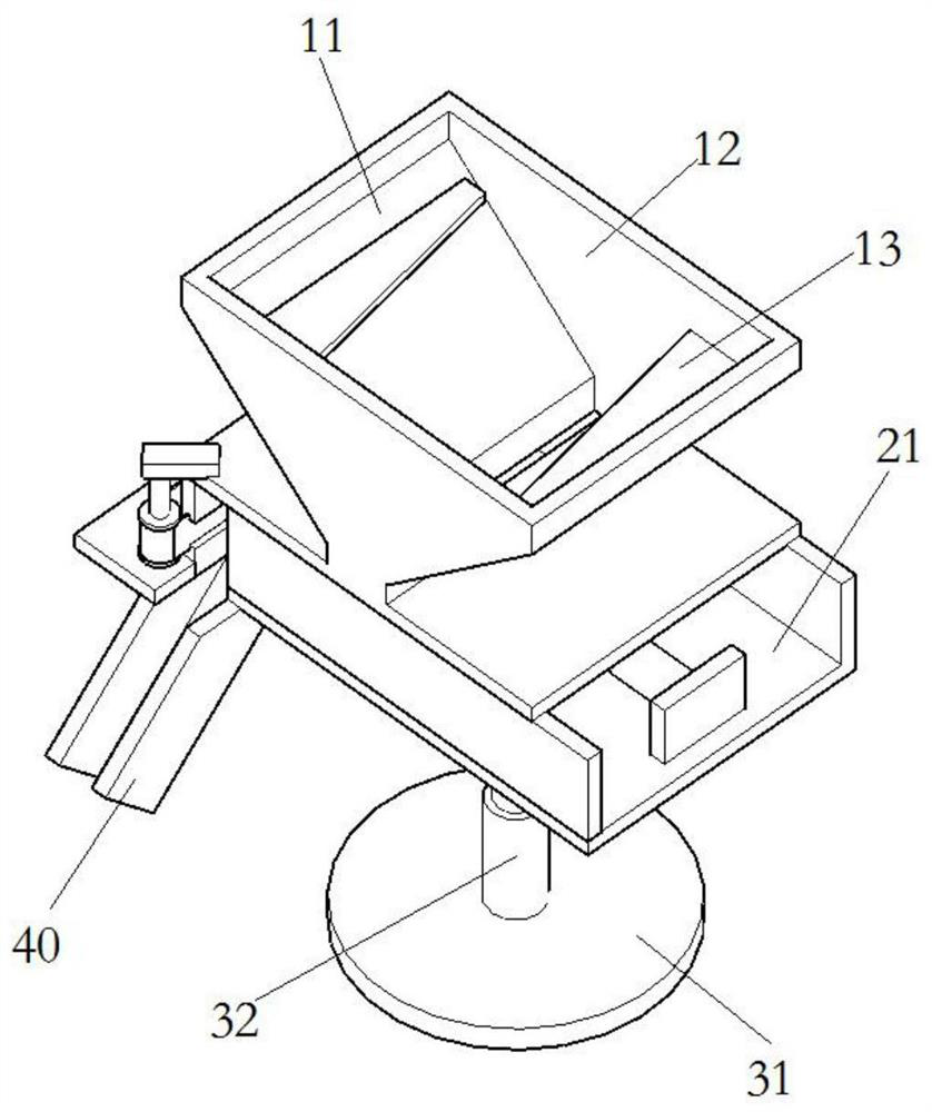
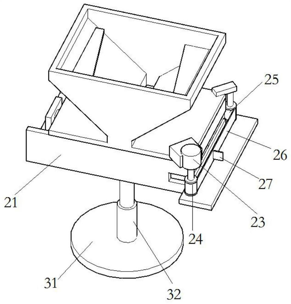
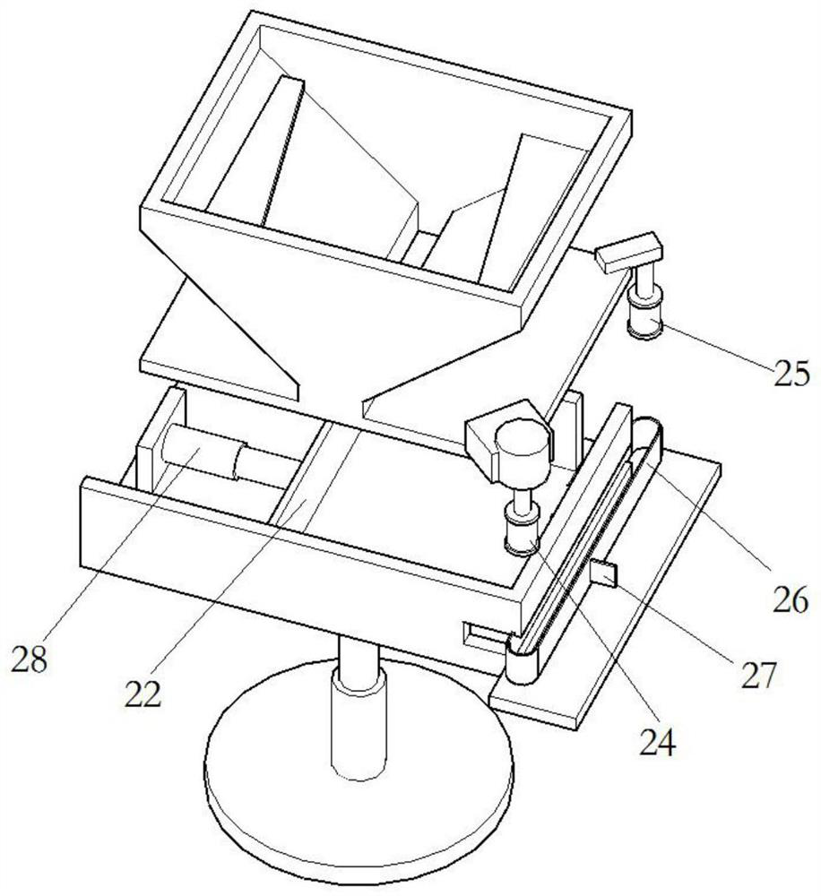
The invention relates to the field of punch press equipment, in particular to an automatic material collecting device for a punch press production line. The automatic material collecting device comprises a material falling assembly and a correcting and pushing assembly, the material falling assembly comprises a material falling port, the material falling port comprises two symmetrically arranged inclined plates and two oppositely arranged side plates, and the lower parts of the inclined plates are drawn close to each other to form a strip-shaped channel; the correcting and pushing assembly comprises a bearing body, a parallel pushing plate and a discharging driving mechanism, the bearing body is arranged below the strip-shaped channel, and the parallel pushing plate is arranged in the bearing body, is parallel to the strip-shaped channel and is used for pushing materials to be close to the edge of the bearing body; and the discharging driving mechanism is used for pushing the materialspushed to the edge of the bearing body by the parallel pushing plate, a discharging opening is formed in the side edge of the bearing body and used for discharging the materials, the situation that workers need to stoop down for a long time when picking up the scattered materials on the ground is avoided, and the materials can be collected in order.

Description

technical field [0001] The invention belongs to the field of punch equipment, in particular to an automatic material collecting device for a punch production line. Background technique [0002] The design principle of the punching machine is to convert the circular motion into a linear motion. The main motor drives the flywheel, and the clutch drives the gear, crankshaft (or eccentric gear), connecting rod, etc. to achieve the linear motion of the slider. From the main motor to the The movement of the connecting rod is a circular motion. There needs to be a transfer point between circular motion and linear motion between the connecting rod and the slider. There are roughly two mechanisms in its design, one is ball type, and the other is pin type (cylindrical type). Through this mechanism, the circular motion Converted to linear motion of the slider. The punch press applies pressure to the material to make it plastically deformed to obtain the required shape and precision. ...

Claims


Application Information

Patent Timeline
Patent Type & Authority Applications(China)
IPC IPC(8): B21D43/20
CPCB21D43/20
Inventor 付家林方加奇王传花刘乾坤赵联赵亚斌
Owner UNIV FOR SCI & TECH ZHENGZHOU
Learn More