Current transformer support frame

A technology of current transformer and support frame, applied in the direction of inductor, transformer/reactor installation/support/suspension, transformer/inductor shell, etc. problems, to facilitate daily inspection and maintenance, avoid insects from entering, and reduce the effect of bird nests

Inactive Publication Date: 2021-02-05
GUIZHOU POWER GRID CO LTD
View PDF8 Cites 1 Cited by
  • Summary
  • Abstract
  • Description
  • Claims
  • Application Information

AI Technical Summary

Problems solved by technology

[0003] At present, the current transformer installed in the transformer adopts the "high-type" layout of the transformer box, and the box is directly hooked on the low-voltage outlet line without fixing
Or fix it with a cross arm or I-beam directly above the transformer, which is high from the ground and close to the high-voltage line, which is not conducive to maintenance and daily observation
There is also an installation method in which the transformer is directly exposed, which has a greater potential safety hazard

Method used


Image

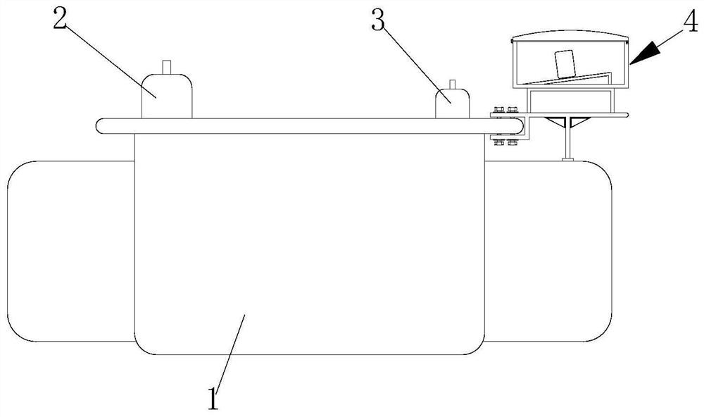
  • Current transformer support frame
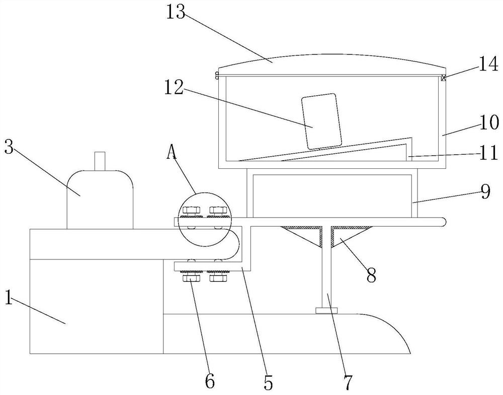
  • Current transformer support frame
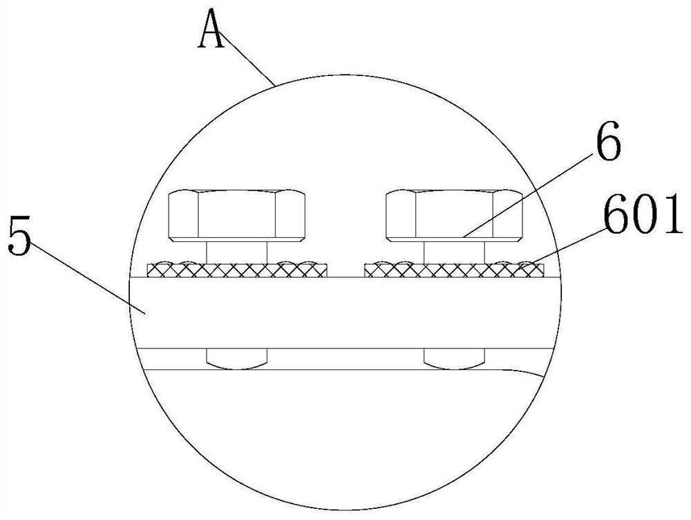
  • Current transformer support frame

Examples


Embodiment Construction

[0026] The following will clearly and completely describe the technical solutions in the embodiments of the present invention with reference to the accompanying drawings in the embodiments of the present invention. Obviously, the described embodiments are only some, not all, embodiments of the present invention.

[0027] Examples of the described embodiments are shown in the drawings, wherein like or similar reference numerals designate like or similar elements or elements having the same or similar functions throughout. The embodiments described below by referring to the figures are exemplary and are intended to explain the present invention and should not be construed as limiting the present invention.

[0028] In describing the present invention, it should be understood that the terms "center", "longitudinal", "transverse", "length", "width", "thickness", "upper", "lower", "front", " Back", "Left", "Right", "Vertical", "Horizontal", "Top", "Bottom", "Inner", "Outer", "Clock...


PUM


Abstract

The invention discloses a current transformer supporting frame, and the frame comprises a transformer; a high-voltage binding post and a low-voltage binding post are arranged at the top of the transformer, and a mutual inductance mechanism is installed on the right side of the top of the transformer. The mutual inductance mechanism comprises a support, a supporting rod, a transformer box and a transformer, and the left side of the support is clamped to a protrusion on the right side of the top of the transformer; bolts are installed at the upper end and the lower end of the left side of the support and are in threaded connection with the left side of the support, an installation base is fixedly connected to the top of the support, and a top transformer box of the installation base is movably installed at the top of the installation base. The three mutual inductors are installed on a fan-shaped sliding rail II, the three mutual inductors form a fan shape, and therefore wires can easilypenetrate through and be easily wired, the mutual inductor box is installed on the installation base, the installation base is fixedly connected to the support, the support is tightly connected to theprotrusion on the right side of the transformer through bolts, and the mutual inductor box is not prone to loosening.

Description

technical field [0001] The invention relates to the technical field of bench-type transformer electric energy measurement, in particular to a current transformer support frame. Background technique [0002] A power transformer is a static electrical device that is used to change an AC voltage (current) of a certain value into another voltage (current) with the same frequency or several different values. The principle of magnetic induction converts a large current on the primary side into a small current on the secondary side for measurement. A current transformer consists of a closed core and windings. Its primary side winding has few turns and is connected in series with the current line to be measured. [0003] At present, the current transformer installed on the transformer adopts the "high-type" layout of the transformer box, and the box is directly hooked on the low-voltage outlet line without fixing. Or fix it with a cross arm or I-beam directly above the transforme...

Claims


Application Information

Patent Timeline
Patent Type & Authority Applications(China)
IPC IPC(8): H01F27/02H01F27/06H01F27/29H01F38/00H01F38/30
CPCH01F27/022H01F27/06H01F27/29H01F38/00H01F38/30
Inventor 赵勇廖翼何毅张德勤陈晓红田山杨颐熊文石炳堂肖道媛田昊仑田飞龙曹裕谋王严娜王龙郑文颜世强邓华张旭沈正康杨小军王志甫赵胜谢菲杨锴刘佳杨昌碑方曦李姜娴
Owner GUIZHOU POWER GRID CO LTD
Why Eureka
Try Eureka