
Protection system for protecting computer application server components

A technology for application servers and protection systems, applied in the field of protection systems for protecting computer application server components, can solve the problems of lack of water leakage protection for water cooling systems, lack of independent protection for components, etc., and achieve the effect of reducing losses

Inactive Publication Date: 2021-02-05
ZHENGZHOU UNIV OF IND TECH
View PDF0 Cites 1 Cited by
  • Summary
  • Abstract
  • Description
  • Claims
  • Application Information

AI Technical Summary

Problems solved by technology

[0009] In view of the above situation, in order to overcome the defects of the prior art, the present invention provides a protection system for protecting computer application server components, which effectively solves the lack of water leakage protection, lack of independent protection for components and lack of dust removal in the existing water cooling system. ability problem

Method used


Image

  • Protection system for protecting computer application server components
  • Protection system for protecting computer application server components
  • Protection system for protecting computer application server components

Examples


Embodiment 1

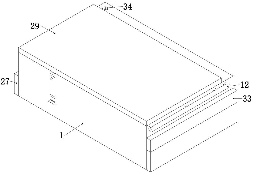
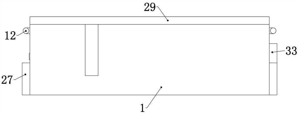
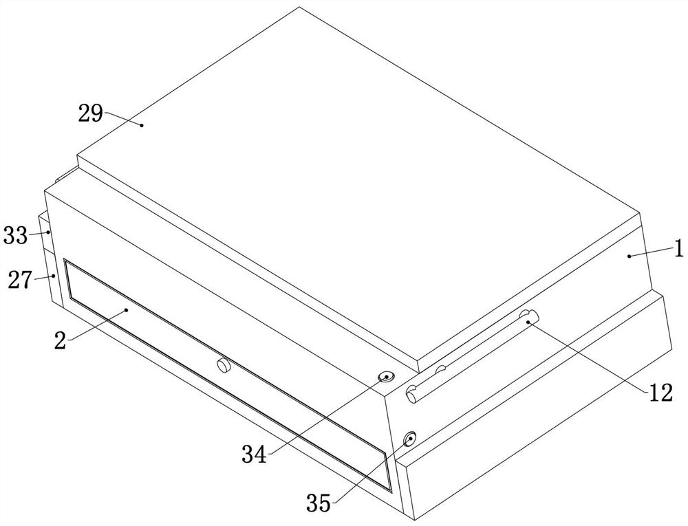
[0044]Embodiment 1. The present invention is a protection system for protecting computer application server components, including a chassis 1. The chassis 1 is a common chassis 1, which is used to provide a fixed foundation for subsequent structures. It is characterized in that the Chassis 1 is divided into equipment compartment 2, mainboard compartment 3, processor compartment 4, storage compartment 5 and other compartments 6. Mainboard compartment 3 is used to store the motherboard, processor compartment 4 is used to store the processor, and storage compartment 5 is used to store storage element, other bins 6 are used to store other components, and the lower ends of the processor bin 4, the storage bin 5 and the other bins 6 are all communicated with the main board bin 3, and this setting makes the processor and the storage element separate Placed in the processor compartment 4 and the storage compartment 5, it can be connected to the main board at the same time. The main boa...

Embodiment 2

[0054] Embodiment 2. On the basis of Embodiment 1, this embodiment provides a wire management structure, so as to ensure that various components will not cause interleaving of various lines when they are raised. Specifically, the processor compartment 4 The side walls of the other warehouses 6 are slidably connected with a wheel frame 17, and the two wheel frames 17 are connected to the cabinet 1 by springs, and the two wheel frames 17 are rotatably connected with a lower thread wheel 18. One end of the wheel frame 17 is hinged with a tension rod 19 whose middle part is slidably connected to the chassis 1, and the upper ends of the two tension rods 19 are rotatably connected with upper wire pulleys 20. This setting can make the wheel frame 17 stretch out to drive When the lower wire wheel 18 is stretched out, the upper wire wheel 20 moves upward synchronously, thereby ensuring that the cable is always in a tensioned state, and the wire wheels on each component bypass the upper ...

Embodiment 3

[0056] Embodiment 3, on the basis of Embodiment 1, the internal air duct 24 arranged under the water tank 11 is fixedly connected in the equipment compartment 2, and the electrostatic dust removal device 25 is fixedly connected in the internal air duct 24, and the electrostatic The dust removal device 25 is a common electrostatic dust removal device 25. The dust-containing gas is electrically separated when passing through the high-voltage electrostatic field of the electrostatic dust removal device 25. After the dust particles are combined with negative ions and charged with negative charges, they tend to discharge and deposit on the surface of the anode, thereby achieving the dust removal effect. It should be noted here that the chassis 1 should be grounded so that in order to prevent the chassis 1 from inductive static electricity, the two ends of the inner air duct 24 are fixedly connected with an exhaust fan 26, and the exhaust fan 26 and the electrostatic precipitator 25 a...


PUM


Abstract

The invention relates to a protection system for protecting computer application server components. The protection system effectively solves the problems that an existing device water cooling system lacks water leakage protection, lacks independent protection for the components and lacks dust removal capacity. According to the technical scheme, the protection system comprises a case body, the interior of the case body is divided into an equipment bin, a mainboard bin, a processor bin, a storage bin and other bins, the lower ends of the processor bin, the storage bin and the other bins are allcommunicated with the mainboard bin, a mainboard supporting plate is vertically and slidably connected in the mainboard bin, and the upper end of the mainboard supporting plate is connected with an electric telescopic rod fixedly connected to the inner side wall of the case body. Upper supporting plates with through holes formed in the middles are connected into the processor bin and the other bins in an up-down sliding mode, storage supporting plates are connected into the storage bin in an up-down sliding mode, and the storage supporting plates and the two upper supporting plates are connected with the adjacent electric telescopic rods. The protection system is simple in structure, realizes independent protection of each component in the server, has a water leakage prevention function and a dust removal and air cooling function of a water cooling system, and is high in practicability.

Description

technical field [0001] The invention relates to the technical field of computer protection, in particular to a protection system for protecting computer application server components. Background technique [0002] A computer server includes a processor, hard disk, memory, system bus, etc., and serves as a node of the network to store and process data and information on the network. Compared with home computer mainframes, computer server chassis, memory, hard drives and motherboards are all larger. Its computing power is also far stronger than that of a home computer host. [0003] While the server has high performance, its calorific value is also much greater than that of a home computer host. In some enterprises that have high requirements for server stability, the heat dissipation of servers usually adopts a combination of air-cooled and water-cooled, or even water-based cooling methods. The main disadvantage of using water-cooled cooling is water leakage at the water-co...

Claims


Application Information

Patent Timeline
IPC IPC(8): G06F1/20G06F1/18B08B5/02B08B6/00
CPCB08B5/02B08B6/00G06F1/181G06F1/20
Inventor 冯学晓李军丹张东坡白艳郭艳辉赵琳
Owner ZHENGZHOU UNIV OF IND TECH
Learn More