


Quick Research
Generate reliable direction feasibility study reports for your R&D in just a few steps.

Technical Q&A
Discover and master advanced knowledge NOW. Basics, ideas, possibilities, all at once.

Find Solutions
As an expert in R&D theories, this can generate solutions to your technical problems instantly.

Evaluate Feasibility
Analyze your overall solution with one click, know your potential R&D risks in advance.

Monitor Landscape
Get weekly tech updates, stay abreast of the latest tech innovations and key insights.
Preparation method and preparation system of low-formaldehyde solid wood composite floor
A technology for a solid wood composite floor and a preparation system is applied in the field of the preparation method and preparation system of a low-formaldehyde solid wood composite floor, which can solve the problems such as the inability to press the bottom plate and the back plate at the same time, so as to ensure the symmetry and integrity, the consistent installation time, The effect of the same installation position
- Summary
- Abstract
- Description
- Claims
- Application Information
AI Technical Summary
Problems solved by technology
Method used
Image

Examples
specific Embodiment approach 1
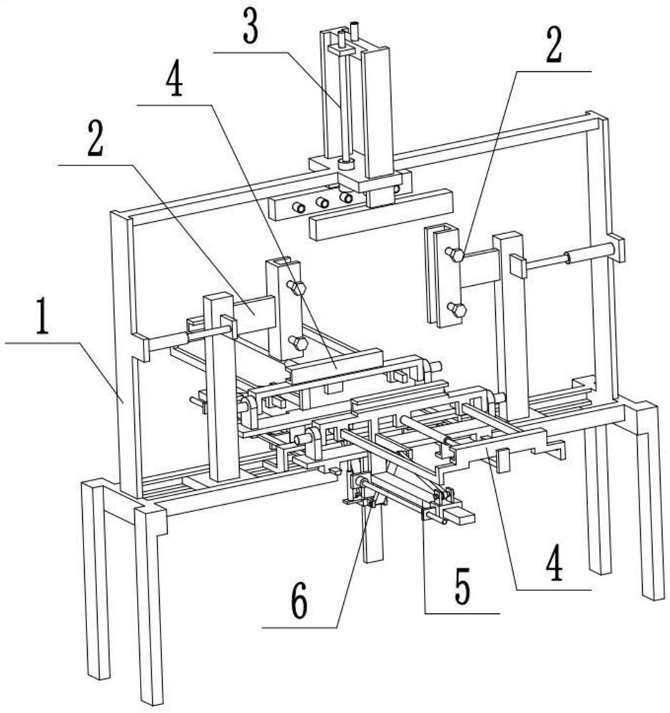
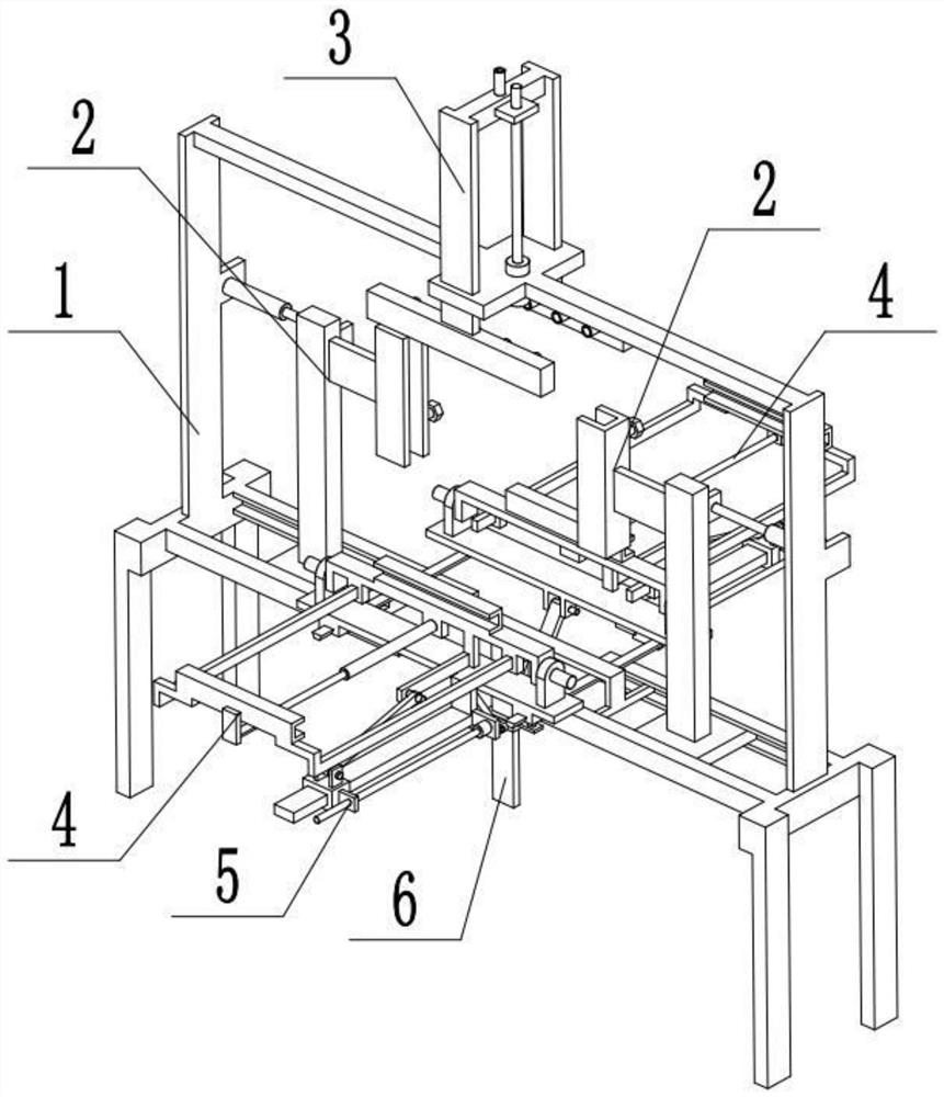
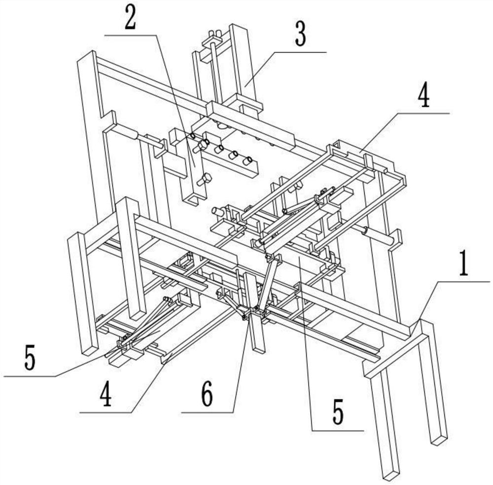
[0033]Combine belowFigure 1-8To illustrate this embodiment, a low-formaldehyde solid wood composite floor preparation system includes a frame 1, a core board fixing member 2, a rubber coating assembly 3, a side board fixing mechanism 4, a side board rotating mechanism 5 and a pressing control mechanism 6. There are two core plate fixing parts 2 described. The two core plate fixing parts 2 are symmetrically arranged at the two ends of the frame 1. The rubber covering assembly 3 is connected to the upper end of the frame 1, and the rubber covering assembly 3 is located on the two cores. Between the plate fixing members 2, there are two side plate fixing mechanisms 4 and two side plate rotating mechanisms 5. The two side plate fixing mechanisms 4 are respectively arranged on the two side plate rotating mechanisms 5, and the two side plate rotating mechanisms 5 The two ends of the pressing control mechanism 6 are symmetrically arranged, and the pressing control mechanism 6 is fixedly co...
specific Embodiment approach 2
[0035]Combine belowFigure 1-8To illustrate this embodiment, the frame 1 includes a door-shaped frame 1-1, an L-shaped bottom frame 1-2, a horizontal chute 1-3, a first motor 1-4, and a first screw 1-5; The two ends of the frame 1-1 are respectively fixedly connected to an L-shaped bottom frame 1-2, the inner sides of the two L-shaped bottom frames 1-2 are respectively provided with a horizontal sliding groove 1-3, and the two core plate fixing parts 2 slide separately In the two horizontal sliding grooves 1-3 within the connection, the first motor 1-4 is fixedly connected to the portal frame 1-1 through the motor frame, and the output shaft of the first motor 1-4 is connected to the first screw through a coupling 1-5, the rubber covering component 3 is connected with the first screw 1-5.
specific Embodiment approach 3
[0037]Combine belowFigure 1-8To illustrate this embodiment, the core plate fixing member 2 includes a T-shaped plate 2-1, a first electric push rod 2-2, and a U-shaped plate 2-3; the T-shaped plate 2-1 is connected to the horizontal sliding groove in a sliding fit In 1-3, the T-shaped plate 2-1 is fixedly connected to the telescopic end of the first electric push rod 2-2, the first electric push rod 2-2 is fixedly connected to one end of the portal frame 1-1, and the U-shaped plate 2 -3 is fixedly connected to the inner end of the T-plate 2-1. When in use, place the core plate between the two U-shaped plates 2-3, and drive the two U-shaped plates 2-3 to approach each other by activating the two first electric push rods 2-2 to clamp and fix the core plate. .
PUM
 Abstract
Description
Claims
Application Information
 - R&D Engineer
- R&D Manager
- IP Professional
- Industry Leading Data Capabilities
- Powerful AI technology
- Patent DNA Extraction
Browse by: Latest US Patents, China's latest patents, Technical Efficacy Thesaurus, Application Domain, Technology Topic, Popular Technical Reports.
© 2024 PatSnap. All rights reserved.Legal|Privacy policy|Modern Slavery Act Transparency Statement|Sitemap|About US| Contact US: help@patsnap.com