
Ultrasonic main shaft, ultrasonic knife handle and ultrasonic machining equipment

An ultrasonic and spindle technology, used in metal processing equipment, turning equipment, metal processing mechanical parts, etc., can solve the problems of inability to automatically change tools, increase costs, and inability to realize the versatility of equipment tool magazines, achieve wireless transmission, reduce The effect of cost of use, good wireless transmission stability and processing effect

Active Publication Date: 2021-02-05
CONPROFE MACHINE TOOLS CO LTD +1
View PDF4 Cites 3 Cited by
  • Summary
  • Abstract
  • Description
  • Claims
  • Application Information

AI Technical Summary

Problems solved by technology

[0004] At present, the main difference between the structure of the ultrasonic spindle and the structure of the ordinary machine tool spindle is that an ultrasonic wireless transmitting device is installed on the front side of the ordinary machine tool spindle, and the ultrasonic wireless transmitting component is a full-ring structure. , the ultrasonic wireless transmitting device will interfere with the or

Method used


Image

  • Ultrasonic main shaft, ultrasonic knife handle and ultrasonic machining equipment
  • Ultrasonic main shaft, ultrasonic knife handle and ultrasonic machining equipment
  • Ultrasonic main shaft, ultrasonic knife handle and ultrasonic machining equipment

Examples


Embodiment 1

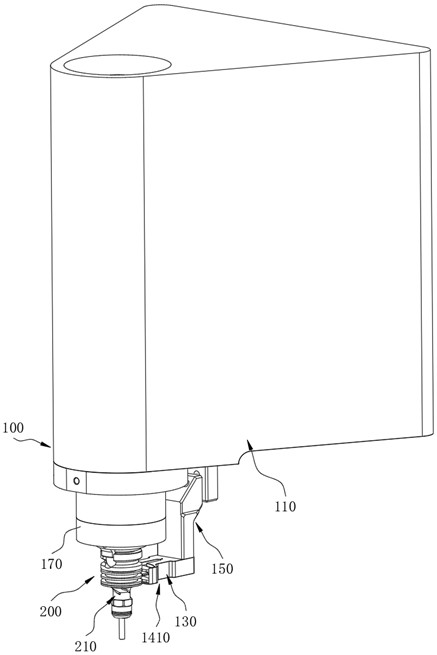
[0115] In the ultrasonic device in the present embodiment, the model of the ultrasonic tool handle 200 is BT30, and correspondingly, the specific structural parameters of the transmitting part 131 and the ultrasonic wireless transmitting unit 140 are:

[0116] α=1.868, V=7176.14, D 1 =46.5,D 2 =67,D 3 =0.35, N=144.

Embodiment 2

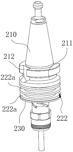
[0118] In the ultrasonic device in this embodiment, the model of the ultrasonic knife handle 200 is BT40, and correspondingly, the specific structural parameter values ​​of the transmitting part 131 and the ultrasonic wireless transmitting unit 140 are:

[0119] α=1.888, V=13602.39, D 1 =65,D 2 =89,D 3 =0.45, N=120.

Embodiment 3

[0121] In the ultrasonic device in the present embodiment, the model of the ultrasonic knife handle 200 is BT50, and correspondingly, the specific structural parameter values ​​of the transmitting part 131 and the ultrasonic wireless transmitting unit 140 are:

[0122] α=1.632, V=19223.93, D 1 =101,D 2 =125,D 3 =0.5, N=130.


PUM

PropertyMeasurementUnit
Axial thicknessaaaaaaaaaa

Abstract

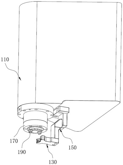
The invention relates to the technical field of ultrasonic machining, in particular to an ultrasonic main shaft, an ultrasonic knife handle and ultrasonic machining equipment. The ultrasonic main shaft comprises a main shaft shell,a rotating shaft assembly, a launching frame and an ultrasonic wireless transmitting unit; the rotating shaft assembly is rotatably arranged in the main shaft shell in apenetrating mode, and a mounting hole is formed in the front end face of the rotating shaft assembly; the launching frame is arranged on the front side of the main shaft shell and comprises a launching part, the launching part is in a non-full-circular-ring shape arranged around the periphery of the rotating shaft assembly, and a first accommodating groove in a non-full-circular-ring shape is formed in the inner side face of the launching part; and the ultrasonic wireless transmitting unit is arranged in the first accommodating groove, and comprises a transmitting coil and a transmitting ferrite. According to the ultrasonic main shaft, by replacing a traditional full-ring type wireless transmitting device with the non-full-ring type ultrasonic wireless transmitting unit, after the ultrasonic knife handle is installed on the ultrasonic main shaft in a matched mode, an avoiding space can be reserved at the knife clamping position of the knife handle body, and therefore the tool magazinecan conduct automatic tool changing, and the universality of the equipment tool magazine can be improved.

Description

technical field [0001] The invention relates to the technical field of ultrasonic processing, in particular to an ultrasonic spindle, an ultrasonic tool handle and ultrasonic processing equipment. Background technique [0002] Ultrasonic machining equipment introduces high-frequency vibration into the rotary motion of the tool, which can not only improve the surface roughness of the machined surface, improve the machining accuracy, but also reduce the cutting resistance and improve the service life of the tool, so it is widely used. [0003] The existing ultrasonic spindle includes fixed parts, rotating parts, bearings and ultrasonic transmission devices. Among them, the fixed parts include related parts such as the main shaft housing and the front end cover. Rotating parts include related parts such as rotating shafts. The ultrasonic transmission device may be an ultrasonic wireless transmitting unit or an ultrasonic wired transmission device. [0004] At present, the ma...

Claims


Application Information

Patent Timeline
IPC IPC(8): B23B19/02B23Q3/12B23Q11/00B23B31/00
CPCB23Q1/70B23Q3/12B23Q11/00B23B31/006
Inventor 颜炳姜李伟秋
Owner CONPROFE MACHINE TOOLS CO LTD
Learn More