
Compact industrial tail gas fine particle efficient removing and cooling device and method

A technology for industrial tail gas and fine particles, applied in separation methods, chemical instruments and methods, heat exchanger types, etc., to meet environmental protection requirements, high separation effect, and compact device structure

Active Publication Date: 2021-02-05
CHINA UNIV OF PETROLEUM (EAST CHINA)
View PDF22 Cites 2 Cited by
  • Summary
  • Abstract
  • Description
  • Claims
  • Application Information

AI Technical Summary

Problems solved by technology

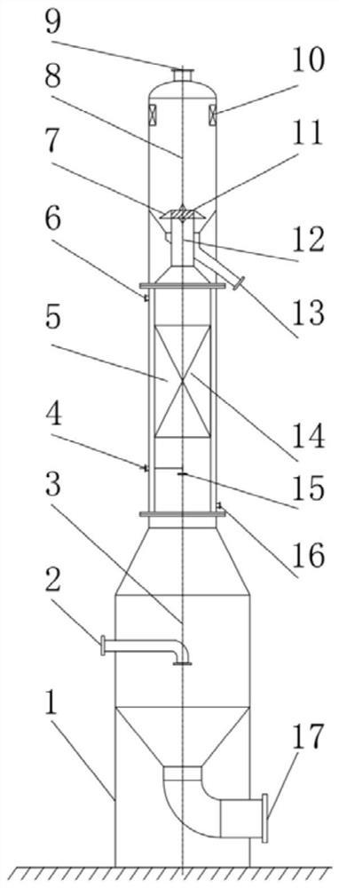
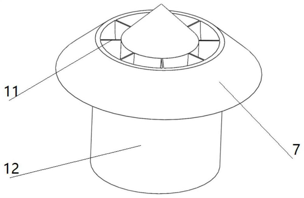
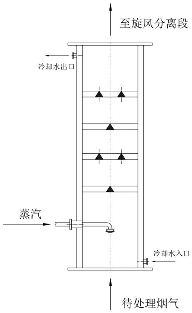
[0005] In order to solve the above-mentioned technical problems, the purpose of the present invention is to provide a compact industrial exhaust fine particle efficient removal and cooling device and method, the device adopts the integrated design of the particle pretreatment unit and the cyclone separation unit, especially in the particle pretreatment unit It is the first time to integrate steam phase change agglomeration and turbulent agglomeration treatment technology, realize the removal of coarse particles and the agglomeration of fine particles in the dusty tail gas, and the cyclone separation unit of the present invention adopts the axial flow cyclone separation with reflective screen The structure of the device can effectively improve the removal efficiency of fine particles; the overall structure of the device is compact, the floor space is small, and the operation is convenient, which solves the problem of high-efficiency and energy-saving removal of fine particle pollutants in industrial tail gas

Method used


Image

  • Compact industrial tail gas fine particle efficient removing and cooling device and method
  • Compact industrial tail gas fine particle efficient removing and cooling device and method
  • Compact industrial tail gas fine particle efficient removing and cooling device and method

Examples


Embodiment Construction

[0028] The present invention will be further described in detail below in conjunction with the accompanying drawings and embodiments.

[0029] The implementation method of the present invention is illustrated by specific specific examples below, and those skilled in the art can easily understand other advantages and effects of the present invention from the content disclosed in this specification. Referring to the accompanying drawings, the structures, proportions, sizes, etc. shown in the accompanying drawings of this specification are only used to match the content disclosed in the specification, for those who are familiar with this technology to understand and read, and are not used to limit the scope of the present invention. Therefore, it has no technical substantive meaning, and any modification of structure, change of proportional relationship or adjustment of size shall still fall within the scope of The technical content disclosed in the present invention must be with...


PUM


Abstract

The invention provides a compact industrial tail gas fine particle efficient removing and cooling device and method, the device comprises a flue gas pretreatment unit and a cyclone separating unit, the flue gas pretreatment unit comprises a gravity settling chamber and a steam phase change chamber, the lower end of the steam phase change chamber is communicated with the upper part of the gravity settling chamber, wherein the steam phase change chamber is divided into a steam phase change section and a turbulence agglomeration section from bottom to top, the device adopts an integrated design of a particle pretreatment unit and the cyclone separating unit, and particularly, a steam phase change agglomeration and turbulence agglomeration treatment technology is firstly fused into the particle pretreatment unit, so that the removal of coarse particles and the agglomeration and growth of fine particles in dust-containing tail gas are realized; the cyclone separating unit adopts an axial flow type cyclone separator structure with a reflecting screen, so that the fine particle removal efficiency is effectively improved; and the device is compact in overall structure, small in occupied area and convenient to operate, and the purpose of efficiently removing fine particle pollutants in industrial tail gas in an energy-saving mode is achieved.

Description

technical field [0001] The invention relates to the field of environmental protection equipment in terms of separation and purification in boiler equipment, and specifically belongs to a compact industrial tail gas fine particle efficient removal and cooling device and method. Background technique [0002] Energy, chemical, metallurgy, thermal power and other pillar enterprises of the national economy will emit a large amount of industrial tail gas during the production process, which will cause great harm to the atmospheric environment and human health. Among the 385 cities monitored in 2016, only 29.6% of them met the air quality standards, and the pollutant emissions mainly come from coal combustion. In response to this problem, my country's environmental protection department has formulated relatively strict legal standards. In addition, the impact of inhalable particulate matter on human health cannot be ignored. Some studies have shown that 100% of the particles with a...

Claims


Application Information

Patent Timeline
IPC IPC(8): B01D45/02B01D45/14F28C3/02
CPCB01D45/02B01D45/14F28C3/02Y02A50/2351
Inventor 王振波茹毅朱丽云
Owner CHINA UNIV OF PETROLEUM (EAST CHINA)
Learn More