Garden deadwood breaking device
A technology for garden dead branches and branches, applied in gardening, gardening tools/equipment, cutting tools, etc., can solve the problems of inflexible transmission, rigid structure, single function, etc.
- Summary
- Abstract
- Description
- Claims
- Application Information
AI Technical Summary
Problems solved by technology
Method used
Image


Examples
Embodiment 1
[0060] A garden dead branch interrupting device, such as figure 1 As shown, it includes a universal wheel 1, a support plate 2, a working plate 3, a branching mechanism 4 and an intermittent cutting mechanism 5, the bottom of the supporting plate 2 is evenly provided with four universal wheels 1, and the top of the supporting plate 2 is provided with a working plate 3. There is a branch punching mechanism 4 on the left side of the top of the working board 3, and an intermittent cutting mechanism 5 is arranged on the branch punching mechanism 4.
[0061] When people want to interrupt the dead branches of the garden, they can use this device for breaking the dead branches of the garden. Nearby, aim at the dead branches on the trees, interrupt the dead branches by the branch breaking mechanism 4, the broken dead branches fall on the working board 3, and then cut the dead branches on the working board 3 through the intermittent cutting mechanism 5. Cut to achieve the effect of cu...
Embodiment 2
[0063] On the basis of Example 1, such as figure 2 with image 3 As shown, the branch beating mechanism 4 includes a first sliding sleeve 41, a connecting slide bar 42, a first spring 43 and a sliding beating bar 44, and the left rear portion of the working plate 3 is provided with two first sliding sleeves 41, and two second sliding sleeves. A slide sleeve 41 is slidably connected with a connecting slide bar 42, the rear portion of the connecting slide bar 42 is wound with a first spring 43, the rear end of the first spring 43 is connected with the connecting slide bar 42, and the front end of the first spring 43 is connected with the first slide bar. Cover 41 is connected, and the sliding type that connects sliding bar 42 front ends is provided with sliding beat bar 44.
[0064]The user places the dead branches on the working board 3 behind the sliding and beating bar 44, and the user pulls the connecting sliding bar 42 backward, and the first spring 43 stretches, driving ...
Embodiment 3
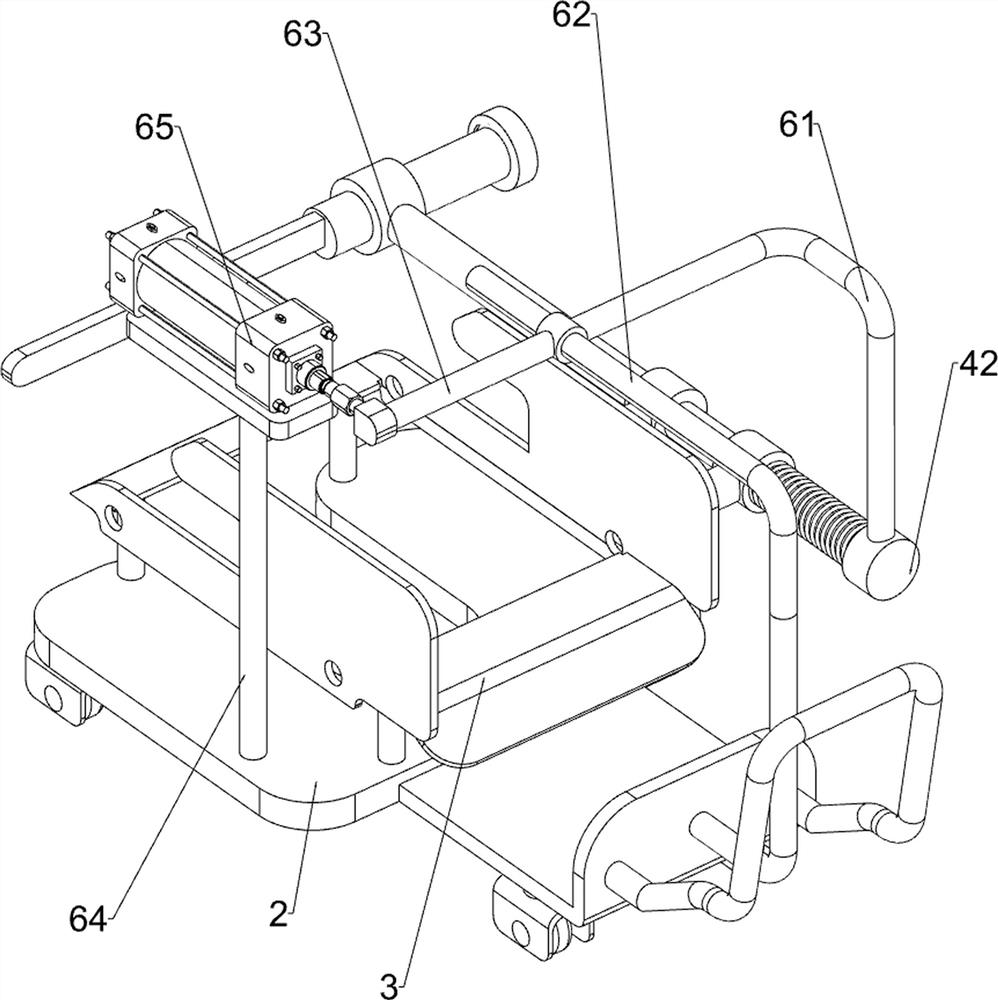
[0068] On the basis of Example 2, such as Figure 4 to Figure 7 As shown, it also includes an automatic cutting and pressing mechanism 6. The top of the support plate 2 is provided with an automatic cutting and pressing mechanism 6. The automatic cutting and pressing mechanism 6 includes a first connecting rod 61, a first fixing rod 62, a fourth sliding sleeve 63, a first Two fixed rods 64 and cylinder 65, the right side of the support plate 2 top is provided with a second fixed rod 64, the second fixed rod 64 top is equipped with a cylinder 65, the middle part of the support plate 2 rear wall is provided with the first fixed rod 62, and the cylinder 65 is telescopic A fourth sliding sleeve 63 is connected to the rod, and the fourth sliding sleeve 63 is slidingly connected with the first fixed rod 62. The left end of the fourth sliding sleeve 63 is provided with a first connecting rod 61, and the first connecting rod 61 is connected with the connecting sliding rod 42. .
[00...
PUM
 Abstract
Description
Claims
Application Information
 - R&D
- Intellectual Property
- Life Sciences
- Materials
- Tech Scout
- Unparalleled Data Quality
- Higher Quality Content
- 60% Fewer Hallucinations
Browse by: Latest US Patents, China's latest patents, Technical Efficacy Thesaurus, Application Domain, Technology Topic, Popular Technical Reports.
© 2025 PatSnap. All rights reserved.Legal|Privacy policy|Modern Slavery Act Transparency Statement|Sitemap|About US| Contact US: help@patsnap.com