Harvesting equipment with impurity removal function

A technology of equipment and functions, applied in the field of harvesting equipment with the function of removing impurities, can solve the problems of reducing the practicability of harvesting machinery, the impact of equipment driving work, and the impact of motor service life, so as to achieve high practicability, improve quality, and prolong service life Effect

Inactive Publication Date: 2021-02-05
张庆然
View PDF6 Cites 0 Cited by
  • Summary
  • Abstract
  • Description
  • Claims
  • Application Information

AI Technical Summary

Problems solved by technology

[0003] When the existing harvesting machinery is working, it usually relies on the motor to drive the wheels to rotate in the field, causing the motor to continue to work, resulting in a higher temperature of the motor, which affects the service life of the motor and increases the chance of damage to the motor due to overheating. probability, which will affect the driving work of the equipment, thereby affecting the harvesting work. Not only that, when the existing harvesting machinery harvests the grains, the grains contain more impurities, so it is necessary to manually remove impurities from the grains , reduces the quality of harvesting, thereby greatly reducing the practicality of existing harvesting machinery

Method used


Image

  • Harvesting equipment with impurity removal function
  • Harvesting equipment with impurity removal function
  • Harvesting equipment with impurity removal function

Examples


Embodiment Construction

[0028] The present invention is described in further detail now in conjunction with accompanying drawing. These drawings are all simplified schematic diagrams, and only illustrate the basic structure of the present invention in a schematic manner, so they only show the configurations related to the present invention.

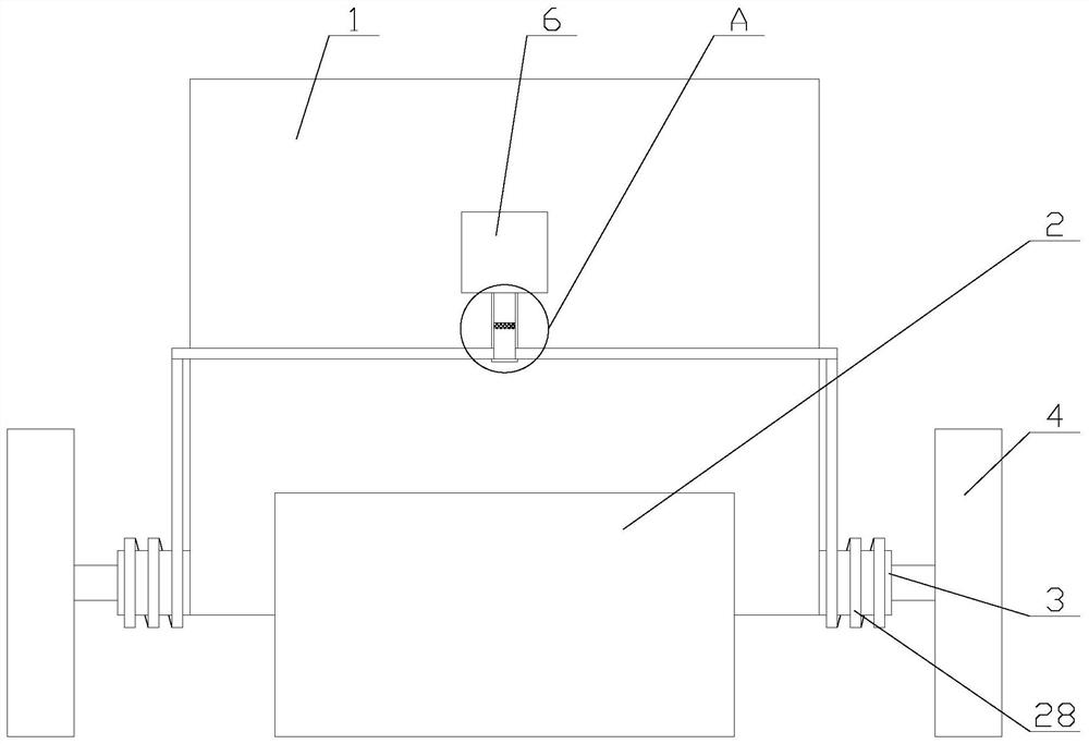
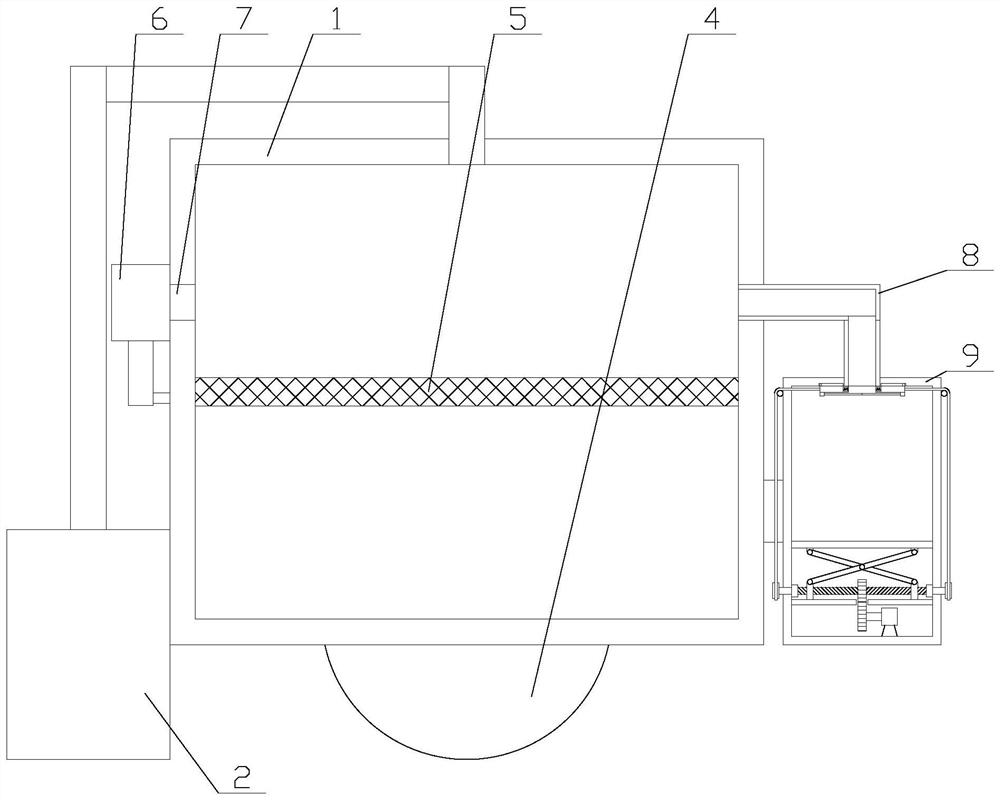
[0029] Such as figure 1 As shown, a harvesting device with impurity removal function includes a main body 1, a harvesting device 2, a filter screen 5 and two traveling devices, the harvesting device 2 is arranged on one side of the main body 1, and the harvesting device 2 is connected to the main body 1 is communicated with the top, the filter screen 5 is horizontally fixed inside the main body 1, and two traveling devices are respectively arranged on both sides of the main body 1 adjacent to the harvesting device 2, and the traveling devices include a first motor 3 and the wheel 4, the first motor 3 is fixed on the main body 1, the first motor 3 is connected t...


PUM


Abstract

The invention relates to harvesting equipment with an impurity removal function. The equipment comprises a main body, a harvesting device, a filter screen, two driving devices, an impurity removal mechanism and a heat dissipation mechanism, and is characterized in that the impurity removal mechanism comprises an air pump, an air inlet pipe, a connecting pipe, a collecting box, a compression assembly and two sealing assemblies; and the compression assembly comprises a pressing plate, a telescopic frame, a power unit, two moving blocks and two driving units, each driving unit comprises a slidingblock, a lead screw and a first bearing, each sealing assembly comprises a sealing plate, a protruding block, an elastic rope, a pull rope and a rotary disc, and the heat dissipation mechanism comprises a branch pipe and two cooling pipes. According to the harvesting equipment with the impurity removal function, the impurity removal function is achieved through the impurity removal mechanism, theimpurity content in grains is reduced, the heat dissipation function on a first motor is achieved through the heat dissipation mechanism, the first motor is prevented from being damaged due to overheating, the service life of the first motor is prolonged, therefore the influence on running of the equipment is avoided, and harvesting work cannot be affected.

Description

technical field [0001] The invention relates to the field of harvesting equipment for agricultural products, in particular to a harvesting equipment with the function of removing impurities. Background technique [0002] Harvesting machinery refers to harvesting machinery that starts to complete several operations (such as harvesting and threshing) at the same time during the harvesting process. [0003] When the existing harvesting machinery is working, it usually relies on the motor to drive the wheels to rotate in the field, causing the motor to continue to work, resulting in a higher temperature of the motor, which affects the service life of the motor and increases the chance of damage to the motor due to overheating. probability, which will affect the driving work of the equipment, thereby affecting the harvesting work. Not only that, when the existing harvesting machinery harvests the grains, the grains contain more impurities, so it is necessary to manually remove im...

Claims


Application Information

Patent Timeline
Patent Type & Authority Applications(China)
IPC IPC(8): A01D41/12A01F12/44A01F12/48A01F12/54H02K9/04
CPCA01D41/12A01F12/44A01F12/48A01F12/54H02K9/04
Inventor 张庆然
Owner 张庆然
Why Eureka
Try Eureka