
Multi-mode control LED dimming constant-current constant-voltage output circuit

A technology of constant current, constant voltage, and output circuit, applied in electrical components and other directions, can solve the problems of inconsistent components LED lights, uneven illumination, slow startup speed, etc., to achieve high energy conversion efficiency, avoid stroboscopic and noise, and start speed. quick effect

Active Publication Date: 2021-02-02
纵领电子(上海)有限公司
View PDF7 Cites 3 Cited by
  • Summary
  • Abstract
  • Description
  • Claims
  • Application Information

AI Technical Summary

Problems solved by technology

Doing this while keeping the dimmer working properly is very difficult and often results in poor performance
Issues can manifest as slow startup, flickering, uneven lighting, or flickering when adjusting light levels
There are also issues with component-to-component inconsistencies and unwanted audible noise from LED lights

Method used


Image

  • Multi-mode control LED dimming constant-current constant-voltage output circuit
  • Multi-mode control LED dimming constant-current constant-voltage output circuit
  • Multi-mode control LED dimming constant-current constant-voltage output circuit

Examples


Embodiment Construction

[0030] The application will be described in further detail below in conjunction with all the accompanying drawings.

[0031] The embodiment of the present application discloses a multiple detection conversion LED dimming constant current output circuit.

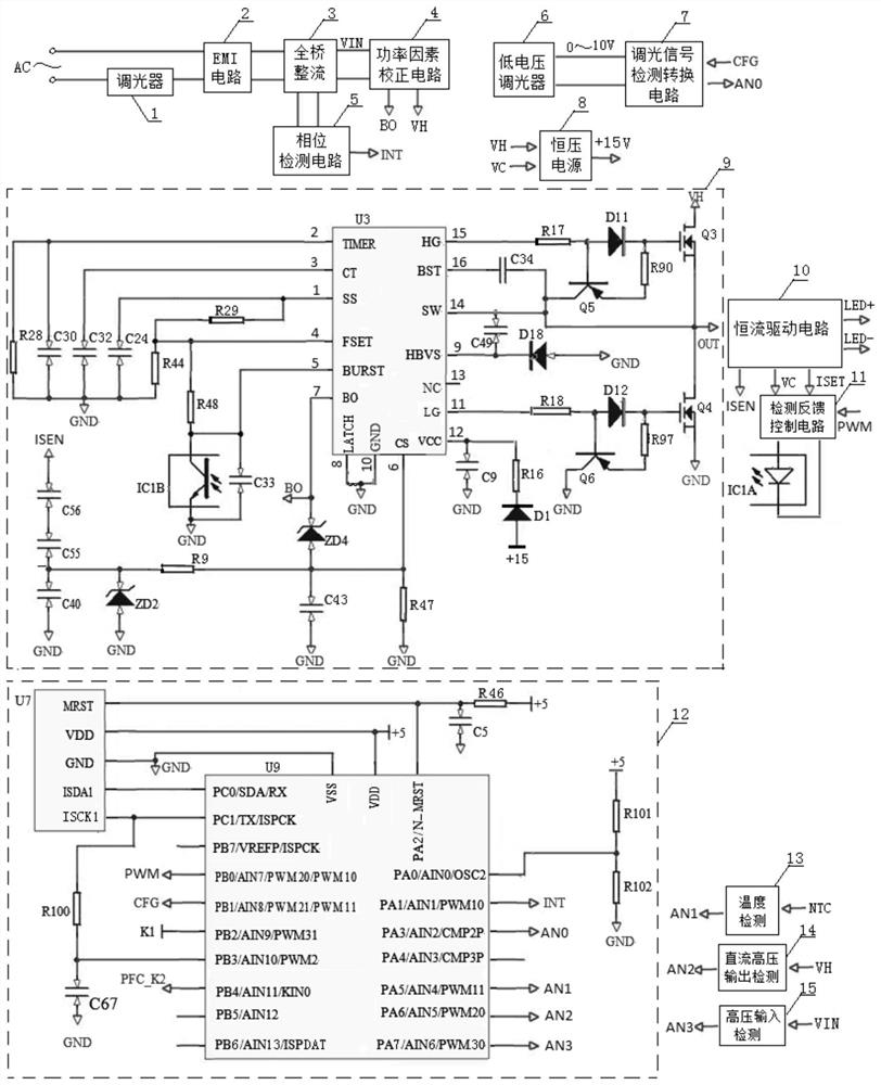
[0032] refer to figure 1 , multi-mode control LED dimming constant current constant voltage output circuit structure diagram, there are many kinds of dimmers, a commonly used dimmer 1 is a pulse width regulator, which is connected in series to the AC input fire wire for adjustment; another commonly used The dimmer is a low-voltage dimmer 6, which outputs a regulated voltage of 0-10V.

[0033] After the AC full voltage (AC100-277V) is input, it passes through the EMI circuit 2 and the full-bridge rectifier circuit 3 in sequence, and outputs the high voltage VIN after filtering and rectifying; the high voltage VIN outputs the DC high voltage VH and the output voltage detection feedback signal BO through the power factor correc...


PUM


Abstract

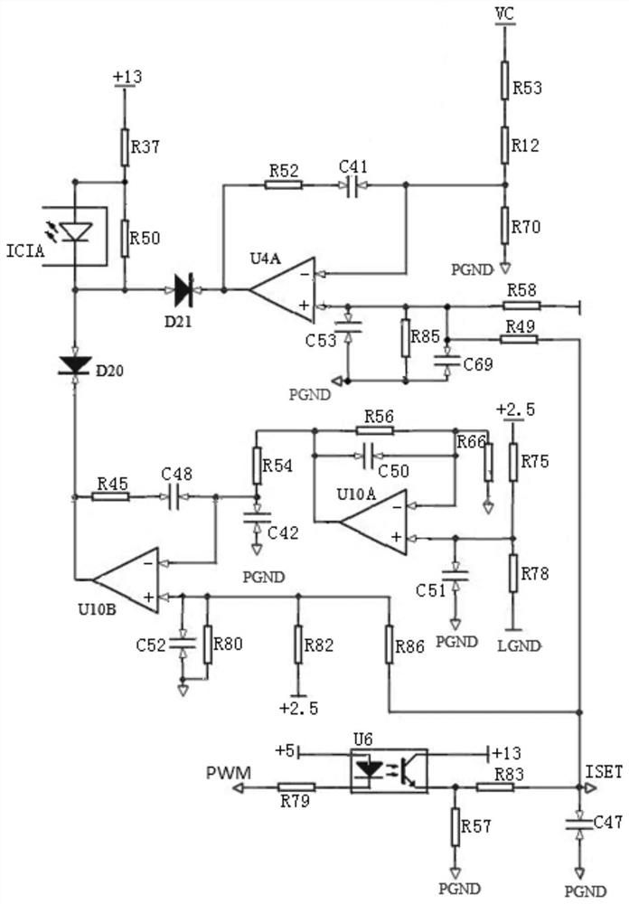
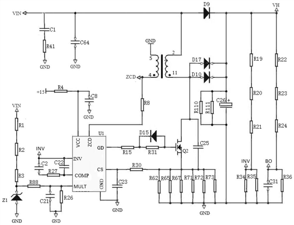
The invention discloses a multi-mode control LED dimming constant-current constant-voltage output circuit which comprises an EMI circuit, a full-bridge rectification circuit, a power factor correctioncircuit, a phase detection circuit, a dimming signal detection conversion circuit, a constant-current power supply, a high-voltage oscillation control circuit, a constant-current driving circuit, a detection feedback control circuit and a signal processing circuit. The resonance frequency conversion control is adopted, according to a connected load, an optocoupler with high interference resistance is adopted to return various feedback signals to a resonance control end, and a power factor correction circuit and a phase detection circuit are combined with a control circuit, so that stable implementation of stepless dimming is ensured. After various dimmers are connected, the stable driving of the LED can be realized in the whole dimming process; the starting speed is high, and no flickering phenomenon exists when the brightness is adjusted; no noise exists in any working state; the driving output can be adjusted according to a load LED lamp connection mode used by a client, so that theuniversality of the circuit is ensured; and the full voltage (AC 100-277V) input is achieved, so that the circuit is suitable for various environments.

Description

technical field [0001] The present application relates to LED lamp dimming driving technology, in particular to a multi-mode control LED dimming constant current and constant voltage output circuit. Background technique [0002] With the development of science and technology, LED technology is also constantly developing, bringing various conveniences to our lives, providing us with various life information, and benefiting us human beings. The application of LED in lighting fixtures is becoming more and more extensive, coupled with the uniqueness superior to traditional lighting methods, in addition to improving the quality of life, improving the efficiency of light sources and prolonging the life of lamps, using its unique dimming function to adjust the color temperature and brightness of lights Changes, and fully achieve energy-saving applications as its greatest advantage. [0003] For an LED lamp to be dimmable, its power supply must be able to analyze the variable phase...

Claims


Application Information

Patent Timeline
Patent Type & Authority Applications(China)
IPC IPC(8): H05B45/14H05B45/34H05B45/345H05B45/355H05B45/325
CPCH05B45/14H05B45/34H05B45/345H05B45/355H05B45/325
Inventor 王汉阳胡逢康
Owner 纵领电子(上海)有限公司
Learn More