
Hybrid converter topological structure for forced current conversion and control method ofhybrid converter topological structure

A topology and hybrid technology, applied in the direction of power transmission AC network, output power conversion device, electrical components, etc., can solve the problems of high cost and increased operating loss

Pending Publication Date: 2021-02-02
GLOBAL ENERGY INTERCONNECTION RES INST CO LTD +1
View PDF0 Cites 0 Cited by
  • Summary
  • Abstract
  • Description
  • Claims
  • Application Information

AI Technical Summary

Problems solved by technology

In addition, in the prior art, there is also a device that can be turned off to forcibly turn off the current to realize the transfer of current. However, due to the long-term conduction of the current by the device that can be turned off, this commutation technology will increase the operating loss and require additional installation Cooling equipment, making the cost of this technical solution higher

Method used


Image

  • Hybrid converter topological structure for forced current conversion and control method ofhybrid converter topological structure
  • Hybrid converter topological structure for forced current conversion and control method ofhybrid converter topological structure
  • Hybrid converter topological structure for forced current conversion and control method ofhybrid converter topological structure

Examples


Embodiment Construction

[0102] The specific implementation manners of the present invention will be further described in detail below in conjunction with the accompanying drawings.

[0103] In order to make the purpose, technical solutions and advantages of the embodiments of the present invention clearer, the technical solutions in the embodiments of the present invention will be clearly and completely described below in conjunction with the drawings in the embodiments of the present invention. Obviously, the described embodiments It is a part of embodiments of the present invention, but not all embodiments. Based on the embodiments of the present invention, all other embodiments obtained by persons of ordinary skill in the art without making creative efforts belong to the protection scope of the present invention.

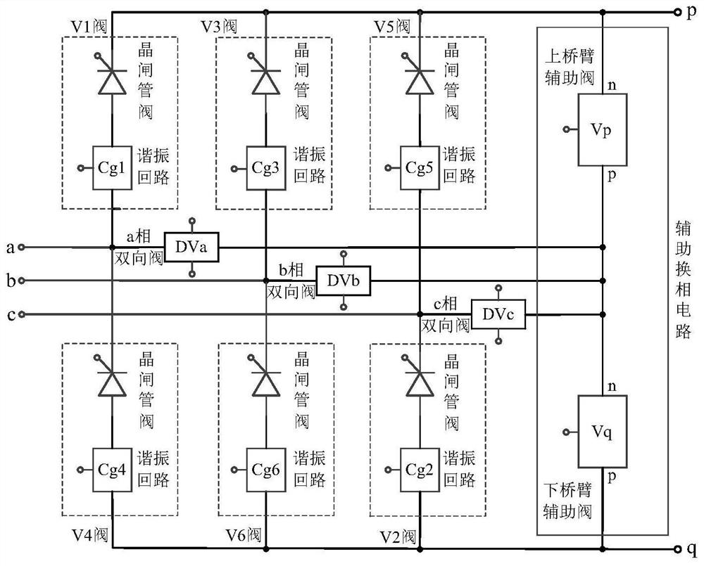
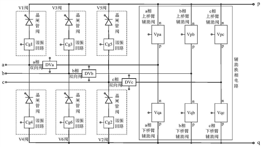
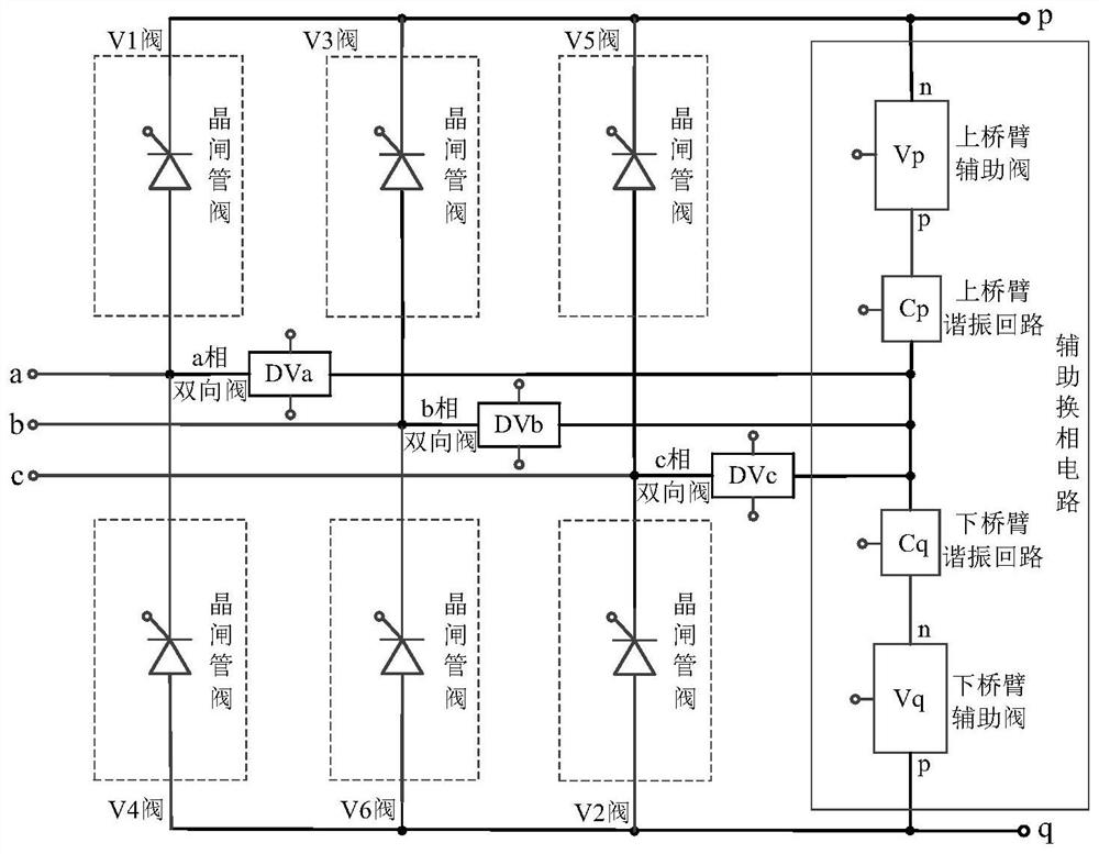
[0104] The invention provides a forced commutation hybrid converter topology, the topology comprising: a three-phase six-leg circuit and a DC side connected in parallel with the three-p...


PUM


Abstract

The invention relates to a hybrid converter topological structure for forced current conversion and a control method of the hybrid converter topological structure. The topological structure comprisesa three-phase six-bridge-arm circuit and an auxiliary commutation circuit which is connected in parallel with the direct current side of the three-phase six-bridge-arm circuit and has forward currentcontrollable turn-off and forward and reverse voltage blocking capabilities; the auxiliary commutation circuit is connected with a connection point of an upper bridge arm and a lower bridge arm of each phase of bridge arm circuit in the three-phase six-bridge-arm circuit through a two-way valve which is arranged on each phase of alternating current bus in a three-phase alternating current bus andhas two-way opening and two-way voltage withstanding capabilities. According to the hybrid converter topological structure for forced current conversion and the control method of the hybrid convertertopological structure of the invention, the auxiliary commutation circuit connected in parallel with the direct current side of the three-phase six-bridge-arm circuit is additionally arranged in the hybrid converter topological structure, so that the commutation fault problem of the hybrid converter topological structure can be solved, and the topological structure is simple to implement and low in cost.

Description

technical field [0001] The invention relates to the technical field of power electronics, in particular to a forced commutation hybrid converter topology and a control method thereof. Background technique [0002] The traditional line commutated converter high voltage direct current (LCC-HVDC) transmission system has the advantages of long-distance large-capacity transmission and controllable active power, and is widely used in the world. However, since the thyristors used in its converters need to rely on the AC system to provide commutation voltage, commutation failures are prone to occur in the event of AC system failure, resulting in a surge in DC current and a rapid loss of DC transmission power. In addition, in recent years, some regional power grids have had multiple DC feed-ins. Once a certain DC line fails to commutate, the coupling of the AC system may lead to chain commutation failures of multiple DC lines, which will bring a negative impact on the safe and stable...

Claims


Application Information

Patent Timeline
Patent Type & Authority Applications(China)
IPC IPC(8): H02J3/36H02M1/32
CPCH02J3/36H02M1/32Y02E60/60
Inventor 高冲张娟娟杨俊魏晓光周建辉盛财旺李婷婷张静
Owner GLOBAL ENERGY INTERCONNECTION RES INST CO LTD
Learn More