Processing cartridge

A process cartridge and drive shaft technology, applied in the field of driving force transmission mechanism and process cartridge, can solve the problems of broken support, easy breakage of the support, inconvenient installation and removal of the process cartridge, etc. pendulum effect

Pending Publication Date: 2021-02-02
JIANGXI YIBO E TECH CO LTD
View PDF2 Cites 0 Cited by
  • Summary
  • Abstract
  • Description
  • Claims
  • Application Information

AI Technical Summary

Problems solved by technology

However, since the supporting portion supporting the engaging portion needs to be elastic and thin, the supporting portion may be broken when the engaging portion transmits the driving force to the main body portion of the flange, resulting in failure to transmit the driving force.
[0004] In order to solve the above-mentioned problem that the supporting part is thin and easy to break, Chinese Patent Publication No. CN208239812U discloses a processing box, which directly fixes the engaging part on the main body of the flange or on the internal supporting part located inside the flange. The drive shaft can be tilted relative to the axial direction. When the process cartridge is installed in the image forming device, the drive shaft will be pushed by the engaging part so that the drive shaft is tilted at a certain angle relative to its own rotation axis to avoid the front end of the drive shaft and The interference between the meshing parts, this structure can solve the problem that the support part is easy to break, in order to prevent the drive shaft from deflecting due to the uneven force on the meshing parts during the rotation of the drive flange, the An elastic forcing part arranged opposite to the engaging part is used to force the drive shaft, but the elastic forcing part needs to rely on elastic force to push, and there is still the possibility that the pushing effect is not ideal. In addition, the elastic forcing part will This increases the difficulty of the deflection of the drive shaft during the process of installing and taking out the process box, which causes inconvenience to the process of installing and taking out the process box

Method used


Image

  • Processing cartridge
  • Processing cartridge
  • Processing cartridge

Examples


Embodiment Construction

[0031] In order to make the purpose, technical solution and technical effect of the embodiment of the present invention clearer, the technical solution of the shadow box of the present invention will be clearly and completely described below in conjunction with the accompanying drawings. Obviously, the described embodiment is only a preferred embodiment of the present invention, rather than all embodiments. Based on the embodiments of the present invention, other embodiments obtained by those skilled in the art without paying creative efforts all belong to the present invention scope of protection.

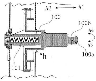
[0032] Such as figure 1 As shown, is a schematic structural diagram of the drive shaft 100 of the image forming apparatus. The drive shaft 100 is approximately cylindrical, and three recesses 100b are evenly distributed on the peripheral surface of the drive shaft 100 (only one is shown in the figure), and a front end 100a is also provided at the front end of the drive shaft 100....


PUM


Abstract

The present invention discloses a processing cartridge. The processing cartridge is detachably mounted in an image forming apparatus including a drive shaft having a recess. The processing cartridge includes a photosensitive drum, a frame supporting the photosensitive drum, and a driving assembly arranged at the axial tail end of the photosensitive drum and used for being meshed with a driving shaft so as to receive driving force and drive the photosensitive drum to rotate; the driving assembly comprises a flange and a power receiving part capable of entering the recess; the power receiving part can force the driving shaft to deflect in the process that the processing cartridge is installed on the image forming apparatus; the driving assembly further comprises a positioning component capable of moving at least in the axis direction of the flange relative to the flange; and the positioning component is used for preventing the driving shaft from deflecting on the axis.

Description

technical field [0001] The present invention relates to a driving force transmission mechanism used in an image forming apparatus and a process cartridge including the driving force transmission mechanism. Background technique [0002] A process cartridge is a cartridge detachably incorporated into the main body of an image forming apparatus, and the cartridge includes, as an integral unit, an electrophotographic photosensitive member and at least processors such as a charger, a developer, a cleaner, etc. one of. Since the process cartridge is detachably mounted with respect to the image forming apparatus main body, maintenance of the apparatus is facilitated. The electronic image forming device using the electrophotographic imaging method works like this: the charger is uniformly charged by the light of the image forming device, and the electrostatic latent image is formed by selective exposure on the electrophotographic photosensitive component, and the latent image is us...

Claims


Application Information

Patent Timeline
Patent Type & Authority Applications(China)
IPC IPC(8): G03G21/18
CPCG03G21/1857G03G21/186
Inventor 胡飞胡亮亮敖仕平郭卫东顾海丰
Owner JIANGXI YIBO E TECH CO LTD
Why Eureka
Try Eureka