Clamp module for numerical control lathe and workpiece clamping method

A fixture module and CNC lathe technology, applied in the field of machine tools, can solve problems such as clamping deflection of shaft parts, affecting product processing accuracy and errors, and achieve the effects of ensuring accuracy, reducing load, and good operation convenience

Pending Publication Date: 2022-07-29
GUANGZHOU ROVMA AUTO PARTS
View PDF0 Cites 0 Cited by
  • Summary
  • Abstract
  • Description
  • Claims
  • Application Information

AI Technical Summary

Problems solved by technology

[0003] Due to the problem of the clamping synchronization of the movable jaws, it also leads to the problem of clamping deflection of the shaft parts. When the existing shaft parts are processed using a three-jaw chuck, the turning tool will be used to check the rough surface of the shaft parts. The main purpose of rough turning is to eliminate the deflection of the shaft parts (readjust the reference coordinate system), and when the shaft parts are clamped twice during the machining process, the deflection caused by clamping will occur. Error, leading to changes in the reference coordinate system, although the error is small in actual operation, but for the field of high-precision machining, its error will greatly affect the processing accuracy and error of the product

Method used


Image

  • Clamp module for numerical control lathe and workpiece clamping method
  • Clamp module for numerical control lathe and workpiece clamping method
  • Clamp module for numerical control lathe and workpiece clamping method

Examples


Embodiment Construction

[0040] The technical solutions in the embodiments of the present invention will be clearly and completely described below with reference to the accompanying drawings in the embodiments of the present invention. Obviously, the described embodiments are only a part of the embodiments of the present invention, rather than all the embodiments. Based on the embodiments of the present invention, all other embodiments obtained by those of ordinary skill in the art without creative efforts shall fall within the protection scope of the present invention.

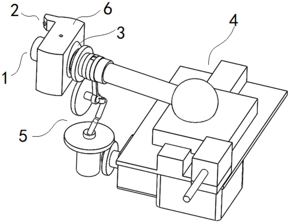
[0041] figure 1 A schematic diagram of the three-dimensional structure of a fixture module for a numerically controlled lathe according to an embodiment of the present invention is shown.

[0042] Specifically, the present invention provides a fixture module for a numerically controlled lathe, which is installed on the main body of the numerically controlled machine tool. Specifically, the main body of the numerically controlled mach...


PUM


Abstract

The invention discloses a clamp module for a numerical control lathe and a workpiece clamping method. The clamp module comprises a clamp head module, a monitoring module, a front end ring sleeve module, a rear end balance module and a driving module. The clamp head module comprises a cylindrical support and a multi-clamping-jaw assembly. The front end ring sleeve module comprises a spherical hinge connecting piece, and the outer wall of the cylinder support is rotationally matched with or fixed to the spherical hinge connecting piece. A limiting surface is arranged on a main body of the numerical control machine tool; the spherical hinge connecting piece is matched in the limiting surface; a balance gravity block in the rear-end balance module is fixedly connected with the cylinder bracket; the driving module is used for driving the cylindrical support to rotate around the axis of the cylindrical support. The monitoring module is used for monitoring the deflection condition of the workpiece clamped by the multi-clamping-jaw assembly when the cylindrical support rotates. According to the clamp module, the rotating axis of the workpiece is adjusted by adjusting the clamp head module used for clamping the workpiece, so that the centering requirement of the target workpiece on the rotating axis is met, and the machining precision of the target workpiece is improved.

Description

technical field [0001] The invention relates to the technical field of machine tools, in particular to a clamp module for a numerically controlled lathe and a workpiece clamping method. Background technique [0002] At present, three-jaw chucks or four-jaw chucks are generally used as workpiece clamping components on CNC machine tools. Three-jaw chucks or four-jaw chucks generally refer to the radial A machine tool attachment that moves, clamps and positions the workpiece. Multiple movable jaws fit on the same toothed disc with plane threads, and the movement of each movable jaw will be synchronized under the action of the toothed disc. Generally, the self-centering accuracy of the three-jaw chuck is 0.05-0.15 mm. [0003] Due to the problem of the clamping synchronization of the movable jaws, it also leads to the problem of clamping deflection of the shaft parts. When the three-jaw chuck is used in the processing of the existing shaft parts, the turning tool is used to al...

Claims


Application Information

Patent Timeline
Patent Type & Authority Applications(China)
IPC IPC(8): B23Q3/06B23Q11/00
CPCB23Q3/06B23Q11/001
Inventor 吴克桦吴雅楠罗应涛邱凯
Owner GUANGZHOU ROVMA AUTO PARTS
Why Eureka
Try Eureka