Cantilever fulcrum jump detection tool and detection method

A jump detection and fulcrum technology, applied in the direction of measuring devices, mechanical measuring devices, mechanical devices, etc., can solve the problems that the turbine rotor cannot get the runout value and blade tip clearance, so as to avoid the inability to check and solve the inability to accurately detect and measure get accurate data

Active Publication Date: 2020-02-07
CHINA HANGFA SOUTH IND CO LTD
View PDF4 Cites 0 Cited by
  • Summary
  • Abstract
  • Description
  • Claims
  • Application Information

AI Technical Summary

Problems solved by technology

[0006] The invention provides a cantilever fulcrum runout detection tool and method to solve the technical problem that the turbine rotor cannot obtain accurate runout values ​​and blade tip clearances during end face detection

Method used


Image

  • Cantilever fulcrum jump detection tool and detection method
  • Cantilever fulcrum jump detection tool and detection method
  • Cantilever fulcrum jump detection tool and detection method

Examples


Embodiment Construction

[0031] It should be noted that, in the case of no conflict, the embodiments in the present application and the features in the embodiments can be combined with each other. The present invention will be described in detail below with reference to the accompanying drawings and examples.

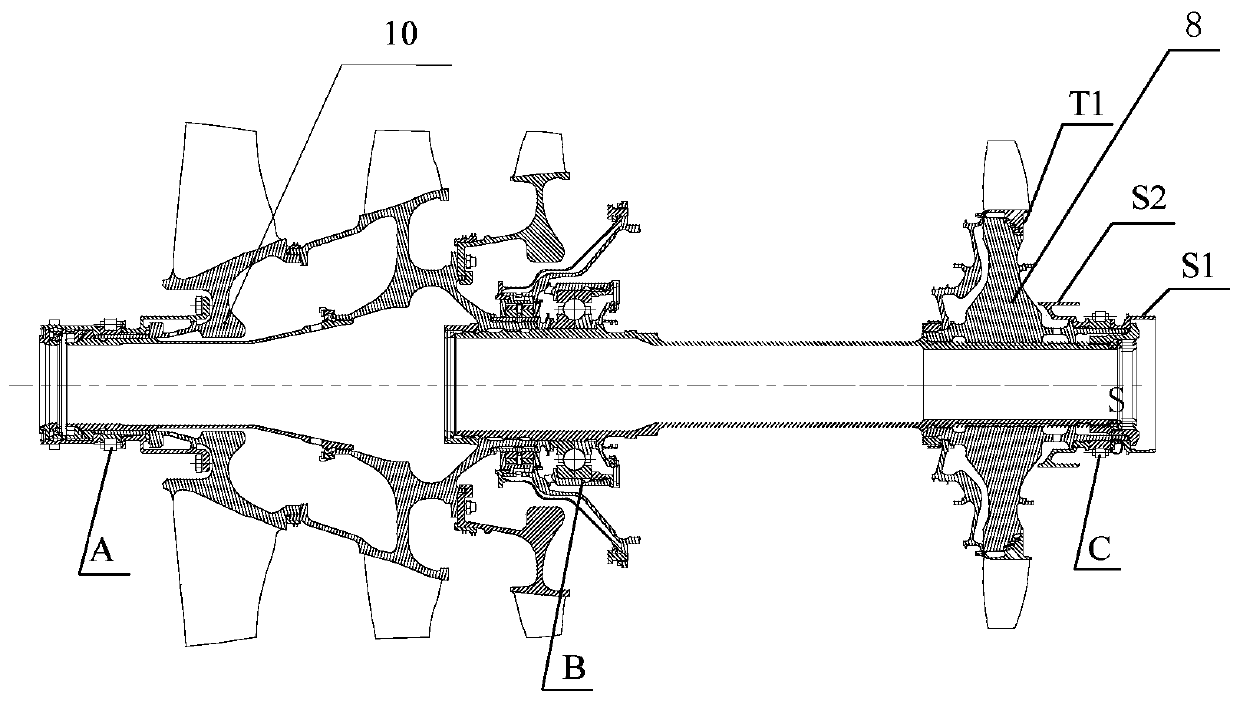
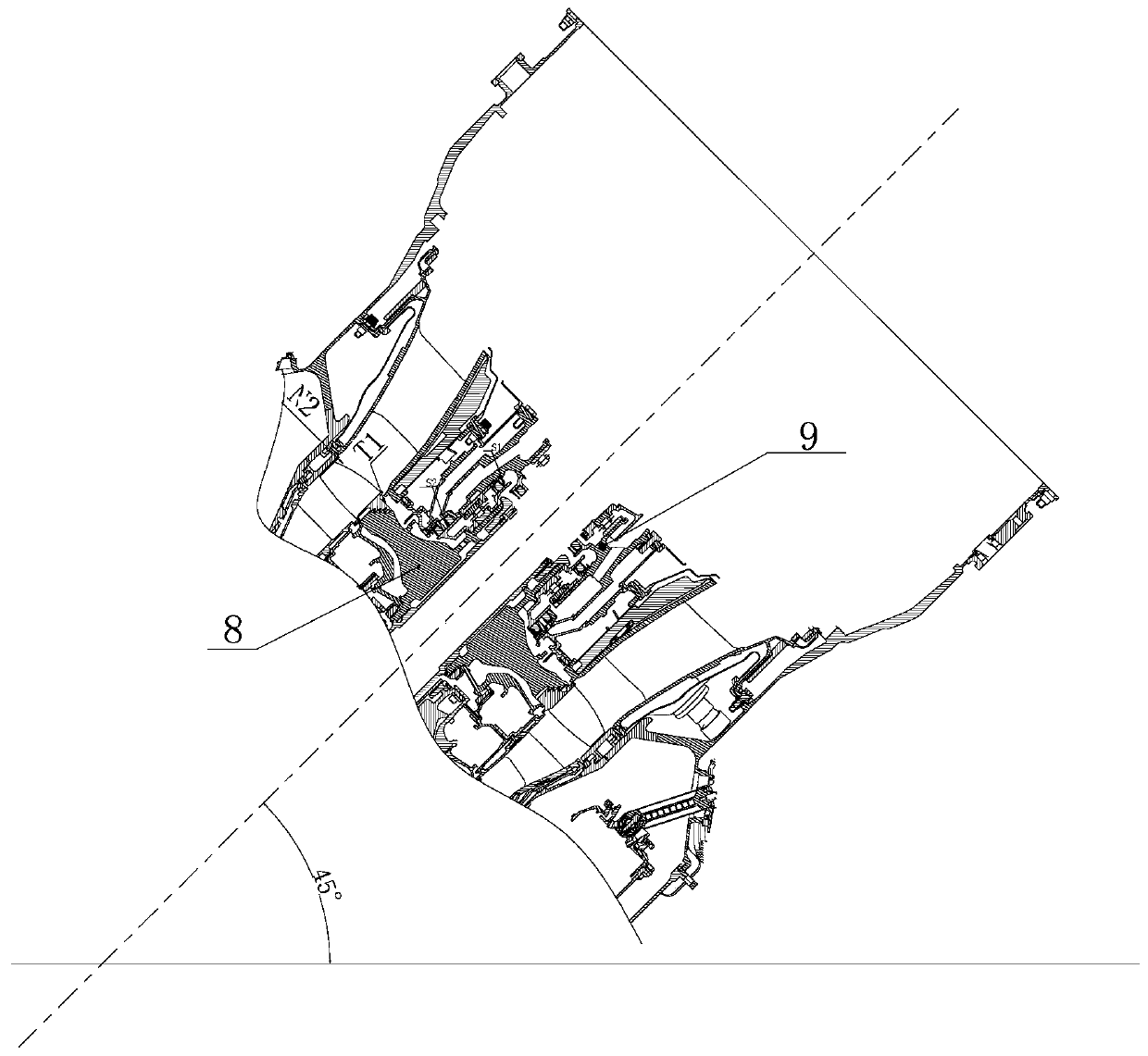
[0032] refer to figure 1 , the preferred embodiment of the present invention provides a cantilever fulcrum jump detection tool, the detection method of the low-pressure turbine rotor run-out value and the blade tip clearance on the existing engine is to detect under the situation that the interstage guide 9 is not installed, but it will There are the following disadvantages: on the one hand, because the low-pressure turbine rotor 8 is connected to the low-pressure compressor through the long shaft, when the support point of the low-pressure turbine rotor 8 is not fixed, the cantilever deflection will occur during the end face detection and blade tip clearance detection, thus As a result, there...


PUM


Abstract

The invention discloses a cantilever fulcrum jumping detecting tool and method. The detecting tool is clamped onto a turbine case and is used for detecting a jumping value and a tip clearance of a low-voltage turbine rotor at a cantilever end of an air compressor; the low-voltage turbine rotor is fixed by a measuring bridge; by a clearance formed in the measuring bridge and an external detecting device, the jumping value and the tip clearance of the low-voltage turbine rotor are detected; and during assembling of an engine, cantilever deflection at the position of a low-voltage turbine can beavoided by adding auxiliary supporting points on the low-voltage turbine rotor, and therefore, measured data are accurate. In addition, the failure of examination after mounting of a mounted interstage guiding device is avoided, the low-voltage turbine rotor is fixed effectively, and the problem that detection is inaccurate due to the fact that a supporting point of the low-voltage turbine rotor deflects is solved.

Description

technical field [0001] The invention relates to the field of aero-engine assembly, in particular to a cantilever fulcrum jump detection tool and a detection method. Background technique [0002] The low-pressure rotor of a new turboprop engine includes a three-stage axial flow compressor, which is connected with a single-stage turbine through a long shaft. Such as figure 1 As shown, the compressor and the turbine are positioned on the shaft with short cylinders, and the low-pressure compressor rotor 10 and the low-pressure turbine rotor 8 are supported on the A, B, and C bearings of the engine, which is a 1-1-1 support form. The low-pressure turbine is cantilevered from the low-pressure compressor, and is fixed with the low-pressure compressor through a splined tie rod shaft and a lock nut. Wherein, the inner ring of the No. C bearing is installed on the low-pressure turbine rotor 8 , and the outer ring of the No. C bearing is installed in the case of the interstage guide ...

Claims


Application Information

Patent Timeline
Patent Type & Authority Patents(China)
IPC IPC(8): G01B21/00G01B21/16G01B5/00
Inventor 程碧玉张鹏飞徐志伟李敏朱彬
Owner CHINA HANGFA SOUTH IND CO LTD
Why Eureka
Try Eureka