
Evaporator for snowflake ice maker

A technology for evaporators and ice machines, which is applied to evaporators/condensers, ice making, ice making, etc. It can solve problems such as the complex sealing structure of evaporators, and achieve the effect of simple structure, simple structure, and improved stability

Pending Publication Date: 2021-02-02
上海明莹制冷设备有限公司
View PDF1 Cites 0 Cited by
  • Summary
  • Abstract
  • Description
  • Claims
  • Application Information

AI Technical Summary

Problems solved by technology

[0007] In order to overcome the above-mentioned shortcoming that the sealing structure of the evaporator in the prior art is too complicated, the present invention provides an evaporator for a snowflake ice machine

Method used


Image

  • Evaporator for snowflake ice maker
  • Evaporator for snowflake ice maker
  • Evaporator for snowflake ice maker

Examples


Embodiment Construction

[0043] The present invention will be further described below in conjunction with the accompanying drawings and embodiments.

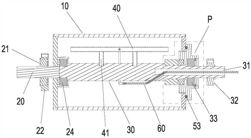
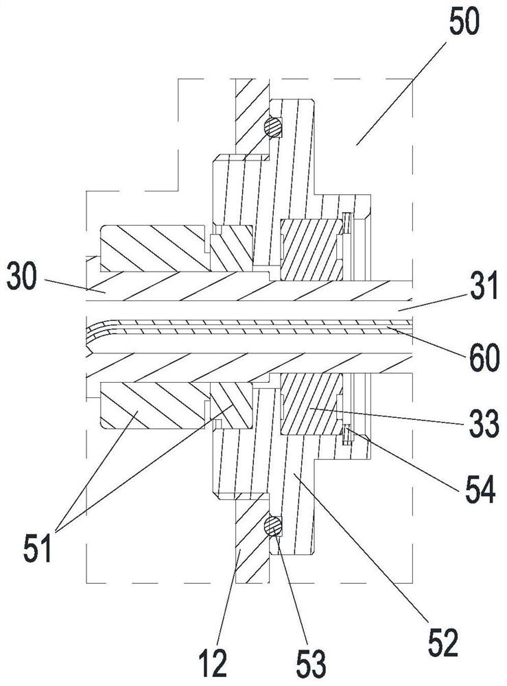
[0044] like figure 1 and figure 2 As shown, the evaporator for the snowflake ice machine of this embodiment includes:

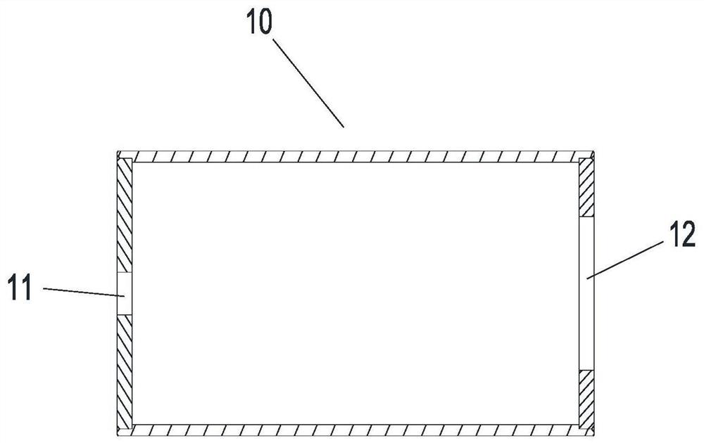
[0045] Cylinder 10, combined image 3 As shown, a fixed shaft 30 is pierced inside, and a first through hole 11 is formed on one side of the cylinder 10 and a drive shaft 20 is formed on one side of the cylinder 10, and a second through hole 12 is formed on the other side of the cylinder 10. The second through hole 12 is formed on the other side of the cylinder 10. A sealing mechanism 50 is arranged in the through hole 12;

[0046] drive shaft 20, combined with Figure 4 As shown, one end is provided with a cup-shaped opening 23, and this end is sleeved inside the cylinder 10 through the first through hole 11 of the cylinder 10, and a first bearing 24 is sleeved in the cup-shaped opening 23. , the drive shaft 20 is located on the...


PUM


Abstract

The invention discloses an evaporator for a snowflake ice maker. The evaporator for the snowflake ice maker comprises a cylinder, a driving shaft, a fixing shaft, and a refrigerant spray pipe, whereinone side of the cylinder is provided with the driving shaft in a penetrating manner; the other side of the cylinder is provided with a sealing mechanism in a penetrating manner; a first bearing is sleeved in a cup-shaped opening in one end of the driving shaft; the driving shaft is provided with a first fixing piece through a second bearing; one end of the fixing shaft is rotatably connected withthe driving shaft in a sleeving mode through a first bearing; the other end of the fixing shaft penetrates out of the outer side of the sealing mechanism; a second fixing piece is arranged on the section, penetrating out of the sealing mechanism, of the shaft body; the refrigerant spray pipe is installed on the fixing shaft in the cylinder through a spray pipe support; and a capillary pipe penetrates through a refrigerant channel in the fixing shaft so as to be connected with the refrigerant spray pipe. According to the evaporator for the snowflake ice maker provided by the invention, the structure is simplified and optimized, compared with the prior art, the defect that the process is complex is overcome, the stability is greatly improved under the long-time operation condition, and meanwhile, the production cost is greatly reduced.

Description

technical field [0001] The invention belongs to the field of ice making machines, in particular to an evaporator for a snowflake ice making machine. Background technique [0002] For example, the application number is 201721263938.8, a rotating cylindrical evaporator for a snowflake ice machine. The refrigerant evaporates and exchanges heat with the rotating cylinder inside the rotating cylinder, and the ice-making water is cooled on the outer wall of the cylinder. Ice, and the ice attached to the outer wall of the cylinder is shoveled down by ice blades to form fine snowflake ice. [0003] The disadvantages of this rotary cylinder evaporator are: [0004] 1. In order to ensure the sealing between the rotating cylinder and the central shaft, a very complex sealing structure is designed, which has a large number of parts and high production costs. [0005] 2. The production process is relatively complicated, which may easily lead to failures. For example, the O-rings set o...

Claims


Application Information

Patent Timeline
Patent Type & Authority Applications(China)
IPC IPC(8): F25B39/02F25C1/00
CPCF25B39/02F25C1/00
Inventor 熊继承熊志承余彭木
Owner 上海明莹制冷设备有限公司
Learn More