Eureka AIR delivers breakthrough ideas for toughest innovation challenges, trusted by R&D personnel around the world.

Offshore garbage collection device

A garbage collection and garbage cavity technology, which is applied in the field of marine garbage collection devices, can solve the problems of reducing garbage collection efficiency, time-consuming and laborious, and garbage classification and collection, and achieve the effect of improving collection efficiency, reducing storage volume, and realizing garbage classification

Active Publication Date: 2021-02-02
ZHEJIANG OCEAN UNIV
View PDF7 Cites 4 Cited by
  • Summary
  • Abstract
  • Description
  • Claims
  • Application Information

AI Technical Summary

Problems solved by technology

[0003] Marine litter has a great impact on the health of the marine ecosystem, and in severe cases, it will threaten the safety of ships sailing at sea. For garbage floating on the sea, marine garbage recycling equipment is usually used to clean up these garbage on a large scale. Because most of the garbage floating on the sea is plastic garbage and iron garbage such as cans, when the marine garbage recycling equipment collects garbage, it cannot sort and collect the garbage. It needs to collect the garbage and then sort it manually, which is time-consuming Laborious; at the same time, most of the garbage floating on the sea is in the form of expansion. After collection, a large storage space is required. The volume of the recycling setting is limited, resulting in a small amount of garbage collected. It needs to go back and forth to load and unload garbage, which reduces the efficiency of garbage collection.

Method used


Image

  • Offshore garbage collection device
  • Offshore garbage collection device
  • Offshore garbage collection device

Examples


Embodiment Construction

[0055] The following are specific embodiments of the present invention and in conjunction with the accompanying drawings, the technical solutions of the present invention are further described, but the present invention is not limited to these embodiments.

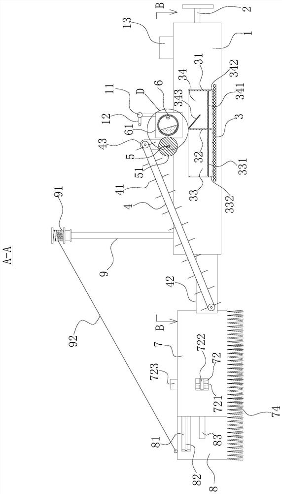
[0056] like Figures 1 to 6 As shown, a marine garbage collection device includes two floating bodies 1, a conveyor belt 4, a material receiving frame 31, a squeezing screening mechanism and a collecting mechanism.

[0057] A connecting block 3 is arranged between the two floating bodies 1 , and a propeller propeller 2 is arranged on the right side of the two floating bodies 1 .

[0058] Preferably, the propeller propeller 2 can be a marine propeller of model YC-017 from Shandong Youchen Machinery Equipment Co., Ltd.

[0059] The conveyor belt 4 is obliquely arranged between the two floating bodies 1, the left end of the conveyor belt 4 is lower than the right end, and the conveyor belt 4 is vertically provided with sever...


PUM


Abstract

The invention provides an offshore garbage collection device, and belongs to the technical field of garbage cleaning. The offshore garbage collection device comprises two floating bodies, a conveyingbelt, a material receiving frame, an extrusion screening mechanism and a collecting mechanism, a connecting block is arranged between the two floating bodies, the conveying belt is obliquely arrangedbetween the two floating bodies, a plurality of push plates are vertically arranged on the conveying belt in the length direction, the material receiving frame is arranged on the upper side face of the connecting block, the material receiving frame is located under the right end of the conveying belt, a partition plate is arranged in the material receiving frame and divides the material receivingframe into a first garbage cavity and a second garbage cavity, the extrusion screening mechanism can flatten garbage falling from the conveying belt and screen out iron garbage in the garbage, and when the two floating bodies move forwards, the collecting mechanism can collect garbage on the left sides of the floating bodies to the position near the left end of the conveying belt. According to theoffshore garbage collection device, marine garbage can be rapidly cleared away, and meanwhile iron garbage can be screened out and recycled.

Description

technical field [0001] The invention belongs to the technical field of garbage cleaning, and relates to a marine garbage collection device. Background technique [0002] Marine litter refers to persistent, man-made or processed solid waste in the marine and coastal environment. [0003] Marine litter has a great impact on the health of the marine ecosystem, and in severe cases, it will threaten the safety of ships sailing at sea. For garbage floating on the sea, marine garbage recycling equipment is usually used to clean up these garbage on a large scale. Because most of the garbage floating on the sea is plastic garbage and iron garbage such as cans, when the marine garbage recycling equipment collects garbage, it cannot sort and collect the garbage. It needs to collect the garbage and then sort it manually, which is time-consuming At the same time, most of the garbage floating on the sea is in the form of expansion. After collection, a large storage space is required. The...

Claims


Application Information

Patent Timeline
Patent Type & Authority Applications(China)
IPC IPC(8): E02B15/10B63B35/32B30B9/30B03C1/18
CPCE02B15/10E02B15/104B63B35/32B30B9/30B03C1/18
Inventor 赖宗元王伟赵成
Owner ZHEJIANG OCEAN UNIV
Why Eureka
Eureka Blog
Learn More