
Supercritical water oxidation reactor and supercritical water oxidation system

A supercritical water oxidation and reactor technology, applied in chemical instruments and methods, oxidized water/sewage treatment, water/sewage treatment, etc., can solve the problems of large consumption of sacrificial layers, complicated operation, hidden safety hazards, etc., to avoid Local enrichment, intensifying heat and mass transfer, and preventing local overheating

Pending Publication Date: 2021-02-02
CHINA NUCLEAR POWER TECH RES INST CO LTD +5
View PDF7 Cites 6 Cited by
  • Summary
  • Abstract
  • Description
  • Claims
  • Application Information

AI Technical Summary

Problems solved by technology

[0003] The supercritical water oxidation reactor disclosed in Chinese patent 106334506A is a tank reactor. A sacrificial layer and a compensation layer are added inside the reactor to reduce the corrosion of the inner layer of the reactor by the supercritical water oxidation reaction. , the sacrificial layer needs to be re-coated on the inner layer of the reactor before it can be put into use next time. Security risks
[0004] Chinese patent 106847358B discloses the application of supercritical water oxidation technology in the treatment of radioactive organic waste liquid. The supercritical water oxidation reactor adopts a tubular reactor, and only a tubular furnace is installed outside the reactor for heating. At the same time, the reactor Without desalination measures, in the supercritical state, inorganic salts will precipitate, and part of the precipitated inorganic salts will adhere to the inner wall of the reactor, which will affect the heat transfer of the reactor and aggravate the corrosion of the equipment. Inorganic salts will block the subsequent pipelines of the system, causing the device to fail to operate normally

Method used


Image

  • Supercritical water oxidation reactor and supercritical water oxidation system
  • Supercritical water oxidation reactor and supercritical water oxidation system

Examples


Embodiment Construction

[0023] Embodiments of the present invention will now be described with reference to the drawings, in which like reference numerals represent like elements.

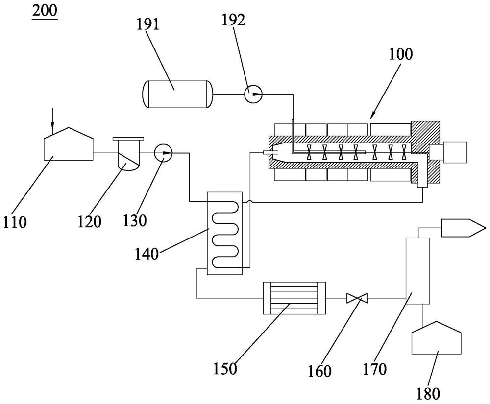
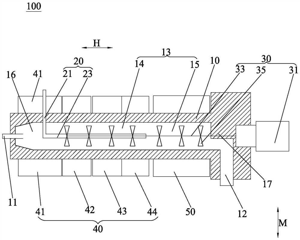
[0024] Please refer to Figure 1-Figure 2 , The supercritical water oxidation system 200 of the present application includes a supercritical water oxidation reactor 100, a feed liquid temporary storage tank 110 connected in sequence, a filter 120, a high-pressure plunger pump 130, a heat exchanger 140, a condenser 150, a back pressure Valve 160, gas-water separator 170 and inorganic waste liquid tank 180, gas-water separator 170 includes a pipeline and a shell side, the outlet of the pipeline is connected to the feed liquid inlet 11, the feed liquid outlet 12 is connected to the inlet of the shell side, and the shell side The outlet communicates with the condenser 150 . Specifically, the organic waste liquid to be treated and the soft water are firstly mixed in a material liquid temporary storage tank 110 according to a ...


PUM


Abstract

The invention provides a supercritical water oxidation reactor which comprises a reactor cylinder, an oxidant inner pipe, a stirring device, and a heater and a cooler which sleeve the reactor barrel.A working area is arranged in the reactor cylinder, and the reactor cylinder is provided with a feed liquid inlet along the axial direction and a feed liquid outlet along the radial direction. The heater has a supercritical area formed corresponding to a heating area of the working area, and the cooler has a sub-critical area formed corresponding to a cooling area of the working area. The oxidantinner pipe comprises a first pipe which is located in the reactor cylinder and arranged in the axial direction and a second pipe which is formed by bending and extending the first pipe in the radial direction and partially extends out of the reactor cylinder, and a plurality of through holes are formed in the second pipe. The stirring device is mounted on the reactor cylinder and is used for stirring the working area so as to uniformly mix an oxidant with an organic waste liquid to be treated. The separation of inorganic salt in the supercritical water oxidation reactor can be effectively reduced, and the corrosion of the supercritical water oxidation reaction to the interior of the supercritical water oxidation reactor is avoided.

Description

technical field [0001] The invention relates to the technical field of supercritical water oxidation reactors, in particular to a supercritical water oxidation reactor and a supercritical water oxidation system. Background technique [0002] Supercritical Water Oxidation (SCWO for short) refers to using supercritical water as the reaction medium under the reaction conditions where the temperature and pressure are higher than the critical temperature (374.3°C) and pressure (22.1MPa) of water, Use air or oxygen as the oxidant to completely oxidize organic pollutants in water into CO 2 and H 2 The process of O et al. Currently, supercritical water oxidation reactors are widely used to treat liquid organic pollutants, but there are some problems. Such as: [0003] The supercritical water oxidation reactor disclosed in Chinese patent 106334506A is a tank reactor. A sacrificial layer and a compensation layer are added inside the reactor to reduce the corrosion of the inner lay...

Claims


Application Information

Patent Timeline
Patent Type & Authority Applications(China)
IPC IPC(8): C02F1/72
CPCC02F1/727
Inventor 袁誉坤林鹏汪栋尹宇发宁刘夏杰李晴李丽丽李坤锋洪振旻王浩宇姜磊赵滢何小平邓才远张惠炜万勇
Owner CHINA NUCLEAR POWER TECH RES INST CO LTD
Learn More