
Automatic forming device for automatic refractory green bricks

A refractory adobe and automatic molding technology, applied in the direction of supply device, clay preparation device, clay mixing device, etc., can solve the problems of manual fatigue, improper masonry method, and low integration degree, so as to ensure smoothness and avoid Sediment blocking effect

Active Publication Date: 2021-02-02
江西丰硕耐火材料有限公司
View PDF4 Cites 2 Cited by
  • Summary
  • Abstract
  • Description
  • Claims
  • Application Information

AI Technical Summary

Problems solved by technology

The main reasons for the low service life of refractory materials are that the production equipment of the manufacturer is backward, and the friction brick press is used for forming. The automation level in the batching, forming, firing and inspection processes is low, the product quality fluctuates greatly, and the size deviation is large; the masonry method is improper.
In use, in order to prevent the refractory bricks from falling off, excessive use of steel plates for locking will result in a large expansion of the refractory material during heating, and excessive pressure will damage the refractory bricks; the degree of fine management is low, etc.
[0005] However, in actual use, due to the low degree of integration of the traditional refractory brick automatic forming device, the operator needs to perform auxiliary operations regularly, and manual operation may easily lead to inaccurate feeding, low work efficiency, and manual labor after long-term work. Inconvenience to use due to fatigue and other conditions

Method used


Image

  • Automatic forming device for automatic refractory green bricks
  • Automatic forming device for automatic refractory green bricks
  • Automatic forming device for automatic refractory green bricks

Examples


Embodiment Construction

[0027] The following will clearly and completely describe the technical solutions in the embodiments of the present invention with reference to the accompanying drawings in the embodiments of the present invention. Obviously, the described embodiments are only some, not all, embodiments of the present invention. Based on the embodiments of the present invention, all other embodiments obtained by persons of ordinary skill in the art without making creative efforts belong to the protection scope of the present invention.

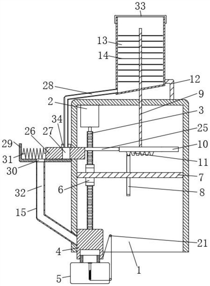
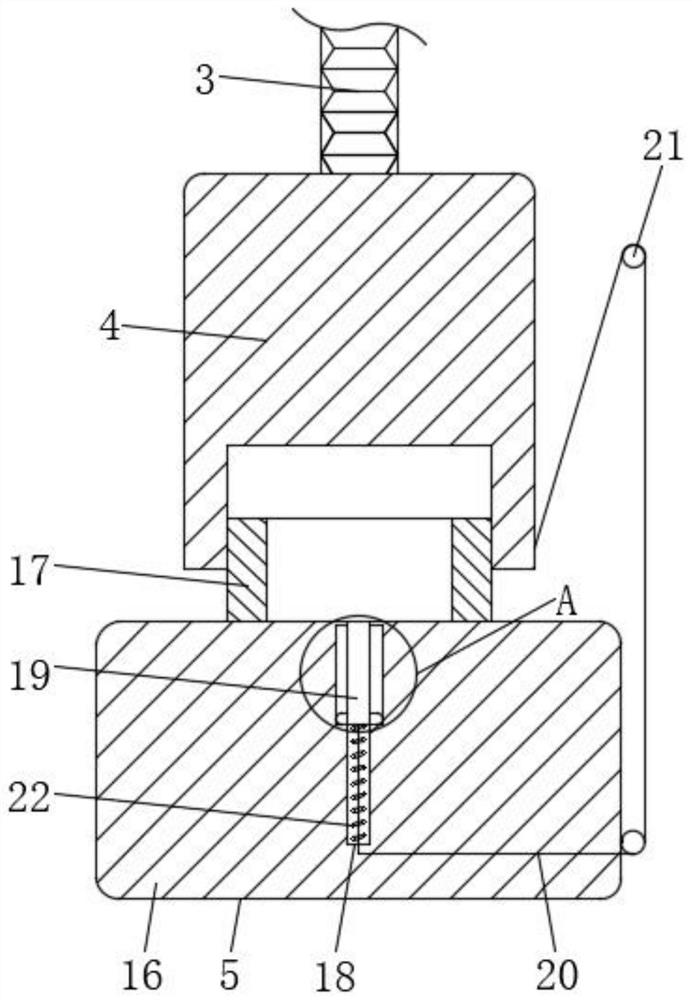
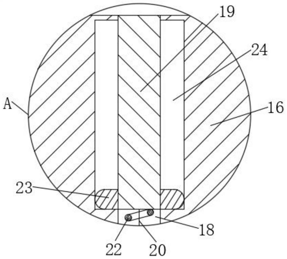
[0028] see Figure 1 to Figure 5 , the present invention provides a technical solution: an automatic forming device for automatic refractory brick adobe, comprising a casing body 1, through which the casing body 1 provides support for the whole device.

[0029] The top of the inner wall of the casing body 1 is fixedly connected with a hydraulic push rod 2. The model of the hydraulic push rod 2 is DYTJ1000, which is powered by an external power supply; the bott...


PUM


Abstract

The invention discloses an automatic forming device for automatic refractory green bricks. The automatic forming device for the automatic refractory green bricks comprises a machine shell body, wherein a hydraulic push rod is fixedly connected to the top of the inner wall of the machine shell body; a toothed plate is fixedly connected to the bottom of an output shaft on the hydraulic push rod; anupper press-fit die holder is fixedly connected to the bottom of the toothed plate; the left side of the upper press-fit die holder is slidably connected with the left side of the inner wall of the machine shell body; a press-fit auxiliary device is arranged below the upper press-fit die holder; the front side of the toothed plate is meshed with a first gear; and the inner wall of the first gear is fixedly connected with a first shaft. According to the automatic forming device for the automatic refractory green bricks provided by the invention, through cooperative use of the structures, the problems that in the actual use process, due to the fact that a traditional automatic forming device for the refractory green bricks is low in integration degree, an operator needs to conduct auxiliaryoperation regularly, and due to manual operation, the feeding amount is not accurate enough, the working efficiency is low, workers are prone to fatigue after working for a long time, and inconvenience is brought to use are solved.

Description

technical field [0001] The invention relates to the technical field of production equipment for refractory bricks, in particular to an automatic forming device for automatic refractory bricks. Background technique [0002] Refractory materials are generally divided into two types, namely unshaped refractory materials and shaped refractory materials. Unshaped refractories are also called castables, which are mixed powdery particles composed of various aggregates or aggregates and one or more binders. When used, they must be mixed with one or more liquids and stirred evenly. Strong mobility. Shaped refractory materials generally refer to refractory bricks, whose shape has standard rules, and can also be temporarily processed when building and cutting according to needs; refractory bricks are referred to as refractory bricks for short. Refractory materials made of refractory clay or other refractory raw materials. Pale yellow or brownish. It is mainly used to build smelting...

Claims


Application Information

Patent Timeline
IPC IPC(8): B28C3/00B28B3/26B28B13/02
CPCB28B3/26B28B13/02B28C3/00
Inventor 吴闻龙
Owner 江西丰硕耐火材料有限公司
Learn More