
PCB automatic machining device and automatic machining process with automatic pin driving and pulling function

An automatic processing and pinning technology, applied in metal processing equipment, metal processing, drilling/drilling equipment, etc., can solve problems such as affecting processing efficiency, difficult for operators, unable to find pin holes, etc., to improve production efficiency and success rate, high control accuracy, and the effect of improving the degree of automation

Active Publication Date: 2021-02-02
CHENGDU JINDALI TECH
View PDF11 Cites 2 Cited by
  • Summary
  • Abstract
  • Description
  • Claims
  • Application Information

AI Technical Summary

Problems solved by technology

The pins reserved on the bakelite board need to be pulled out one by one manually, which is time-consuming and labor-intensive
At the same time, as the types of PCBs processed on bakelite boards increase, the cumulative number of pin holes on bakelite boards will increase, which will make it difficult or impossible for operators to find the punched pin holes.
In addition, there will also be situations where the position of the pin hole is wrongly punched, which will cause the wrong pin hole on the pin, resulting in the failure of the PCB to fit together, which will greatly affect the processing efficiency.
[0005] After the pins are pulled out, different types of pins need to be classified and managed, which will have a great impact on work efficiency

Method used


Image

  • PCB automatic machining device and automatic machining process with automatic pin driving and pulling function
  • PCB automatic machining device and automatic machining process with automatic pin driving and pulling function
  • PCB automatic machining device and automatic machining process with automatic pin driving and pulling function

Examples


Embodiment Construction

[0048] The present invention will be further described in detail below in conjunction with the accompanying drawings and specific embodiments.

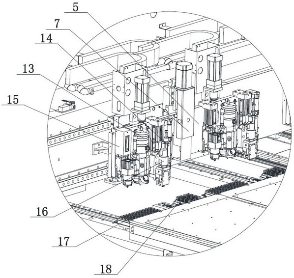
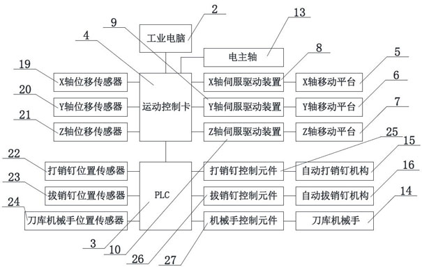
[0049] Such as Figure 1-Figure 3 As shown, a PCB automatic processing equipment with the function of automatically pulling out pins includes a device body 1, an industrial computer 2, a motion control card 4, a PLC 3, and an X-axis that is set at one end of the device body 1 and moves along the horizontal direction. Platform 5, a Y-axis mobile platform 6 arranged below the X-axis mobile platform 5 and perpendicular to the X-axis mobile platform 5, a Z-axis arranged vertically on the X-axis mobile platform 5 and perpendicular to the Y-axis mobile platform 6 The mobile platform 7, is connected with the X-axis mobile platform 5 and drives the X-axis servo driver 8 that drives the X-axis mobile platform 5 to move, is connected with the Y-axis mobile platform 6 and drives the Y-axis servo driver 9 that drives the Y-axis mobile platform 6 ...


PUM


Abstract

The invention discloses a PCB automatic machining device with an automatic pin driving and pulling function. The PCB automatic machining device comprises a device body, an industrial computer, a motion control card, a PLC, an X-axis moving platform, a Y-axis moving platform, a Z-axis moving platform, an X-axis servo driving device, a Y-axis servo driving device and a Z-axis servo driving device. An electric main shaft, a tool magazine mechanical hand, an automatic pin driving mechanism and an automatic pin pulling mechanism are arranged on the Z-axis moving platform. A pin magazine and a toolmagazine are arranged at the end, close to the X-axis moving platform, of a work table. The industrial computer is connected with the motion control card, and the PLC is connected with the motion control card. The PLC is connected with the automatic pin driving mechanism, the automatic pin pulling mechanism and the tool magazine mechanical hand, and the electric main shaft is connected with the motion control card. By means of the PCB automatic machining device, automation and precision of the whole process of pin driving and pulling are achieved, and the automation degree of the PCB machiningdevice can be greatly improved.

Description

technical field [0001] The invention belongs to the field of PCB processing, and in particular relates to a PCB automatic processing equipment and an automatic processing technology with the function of automatically pulling out pins. Background technique [0002] At present, the PCB needs to be positioned and reprocessed in the early stage of processing. The positioning method is through pin positioning. Generally, pins of several diameters are used according to the design process of the PCB, so as to ensure that the PCB will not shift during processing. . [0003] The way of conventional pins on the PCB is manual pinning, the main way is: first use the electric spindle to drill pin holes on the bakelite board on the top surface of the workbench, and then the operator uses a hammer to drive the pins into the pin holes one by one. Then use the positioning holes on the PCB to fit the pins on the bakelite board to ensure that the PCB is fixed under the pins, and then carry ou...

Claims


Application Information

Patent Timeline
Patent Type & Authority Applications(China)
IPC IPC(8): B23B41/00B23P19/02B23Q3/157
CPCB23B41/00B23P19/02B23Q3/157H05K3/0044H05K2203/167
Inventor 马飞达龚泽辉王丽辉王关键陈毅程忠向方勇
Owner CHENGDU JINDALI TECH
Learn More