Floating boring cutter bar for deep holes
A boring tool and deep hole technology, which is applied in the field of floating boring tool holder for deep holes, can solve the problems of unfavorable processing, substandard deep hole accuracy, boring lathes, etc., and achieves the effect of improving work stability.
- Summary
- Abstract
- Description
- Claims
- Application Information
AI Technical Summary
Problems solved by technology
Method used
Image
Examples
Embodiment 1
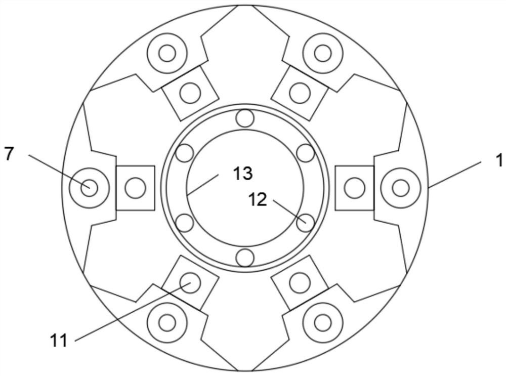
[0025] Embodiment one, with reference to Figure 1 to Figure 6 : A floating boring bar for deep holes, including a tool holder 1, the outer wall of the tool holder 1 is provided with six discharge grooves 2 along the circumferential surface, and the inner walls of the six discharge grooves 2 are all slidingly embedded with scrapers 3 , through the scraper 3, it is possible to quickly discharge debris and waste water. The inner side of the knife seat 1 is provided with six reset chute 5, and the tops of the six reset chute 5 are connected to the bottom of the discharge groove 2 At the end axis, and the center of both sides of the inner wall of the six reset chute 5 is fixedly provided with a limit rod 11, and the outer wall of the limit rod 11 is slidingly sleeved with a return spring 6, through the reset chute 5, limit rod 11 and reset The spring 6 can realize the stable driving and reset of the scraper 3, avoid being stuck on the inner side of the discharge groove 2, and impr...
Embodiment 2
[0026] Embodiment two, refer to Figure 1 to Figure 6 : the outer wall of the knife seat 1 is provided with six groups of auxiliary grooves 4, and one side of the six groups of auxiliary grooves 4 is connected to one side of the discharge groove 2, and one side of the inner wall of the pressure groove 8 is embedded with a pressure cylinder 9, and One end of the pressurized cylinder 9 is communicated with a dredging pipe 21. Through the dredged pipe 21, a stable supply of cooling medium can be realized, and the other end of the pressurized cylinder 9 is communicated with an external cooling liquid supply device. The top of the dredged pipe 21 A limiting tube 20 is communicated, and one side of the outer wall of the limiting tube 20 is embedded in the inner side of the pressure groove 8, and the top of the limiting tube 20 is communicated with six supply tubes 22, through which the nozzle can be cleaned stably The cleaning liquid pressure of 7 is to ensure that the cooling liqui...
Embodiment 3
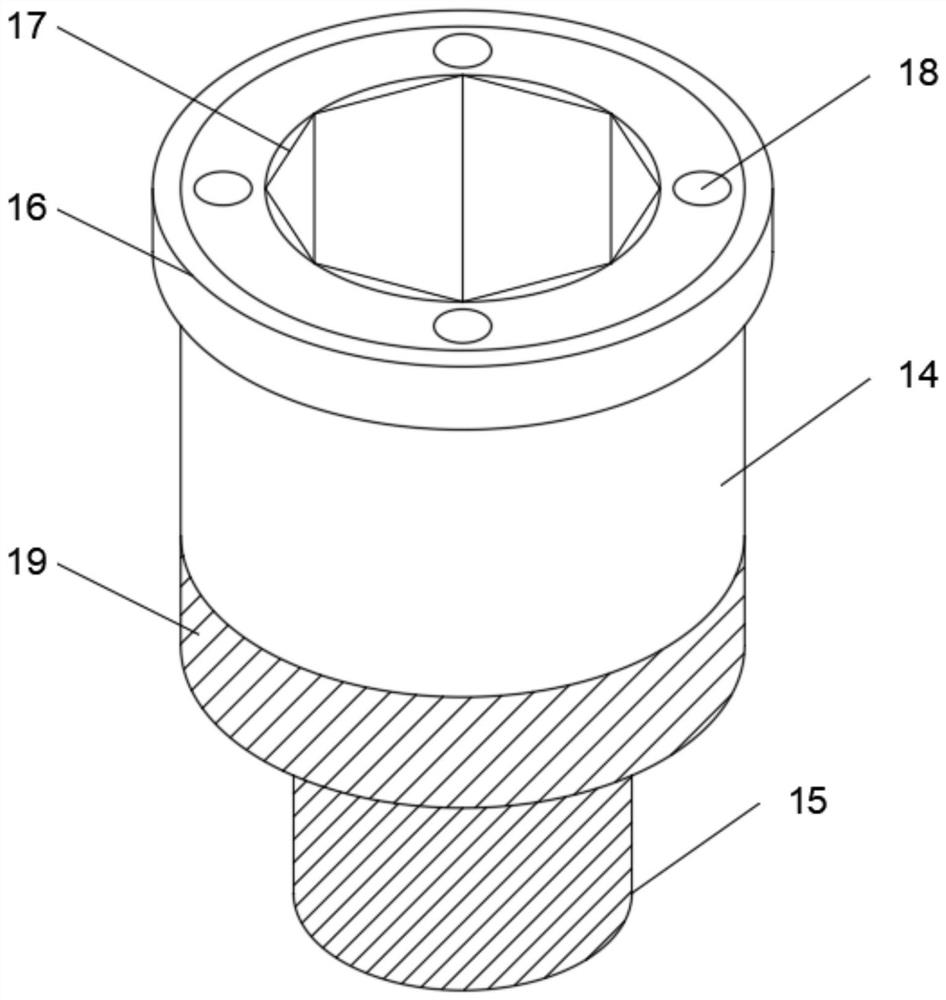
[0027] Embodiment three, refer to Figure 1 to Figure 6 : the top of the installation rod 14 is provided with a plurality of cooling nozzles 18, the inner wall of the installation groove 13 is provided with a plurality of branch holes 12, and one end of the plurality of branch holes 12 is connected to the restricting tube 20, through the branch holes 12 and the cooling nozzle 18 , can realize stable cooling spray on the boring tool, and the other end of a plurality of tributary holes 12 is connected to one end of the cooling nozzle 18, and the top edge of the outer wall of the installation rod 14 is sleeved with a gasket 16, and the gasket 16 is matched with the installation groove 13, and the end of the knife holder 1 away from the scraper 3 is provided with a fixed base 10, and the edge of the outer wall of the fixed base 10 protrudes outward, and the outer wall of the installation rod 14 is provided with an external thread 19, and the installation The bottom end of the rod ...
PUM
 Abstract
Description
Claims
Application Information
 - R&D Engineer
- R&D Manager
- IP Professional
- Industry Leading Data Capabilities
- Powerful AI technology
- Patent DNA Extraction
Browse by: Latest US Patents, China's latest patents, Technical Efficacy Thesaurus, Application Domain, Technology Topic, Popular Technical Reports.
© 2024 PatSnap. All rights reserved.Legal|Privacy policy|Modern Slavery Act Transparency Statement|Sitemap|About US| Contact US: help@patsnap.com


