
Oil-water separation device based on air floatation method

An oil-water separation device and air flotation technology, applied in separation methods, liquid separation, chemical instruments and methods, etc., can solve the problems of incomplete oil-water separation, insufficient number of tiny bubbles, and insufficient foam removal, etc. The effect of bubble bonding

Pending Publication Date: 2021-02-02
WUXI HI TECH ENVIRONMENTAL PROTECTION EQUIP TECH
View PDF5 Cites 3 Cited by
  • Summary
  • Abstract
  • Description
  • Claims
  • Application Information

AI Technical Summary

Problems solved by technology

[0004] The above-mentioned patent also has the following disadvantages: the removal of the froth is not complete enough, and some of the froth still floats on the liquid surface; the combination of oil and tiny air bubbles is not complete enough, and part of the oil may settle at the bottom of the separation barrel, resulting in oily water The separation is incomplete; and aeration is only performed when the water enters. If the separation time is long, the number of tiny air bubbles may not be enough.

Method used


Image

  • Oil-water separation device based on air floatation method
  • Oil-water separation device based on air floatation method
  • Oil-water separation device based on air floatation method

Examples


Embodiment 1

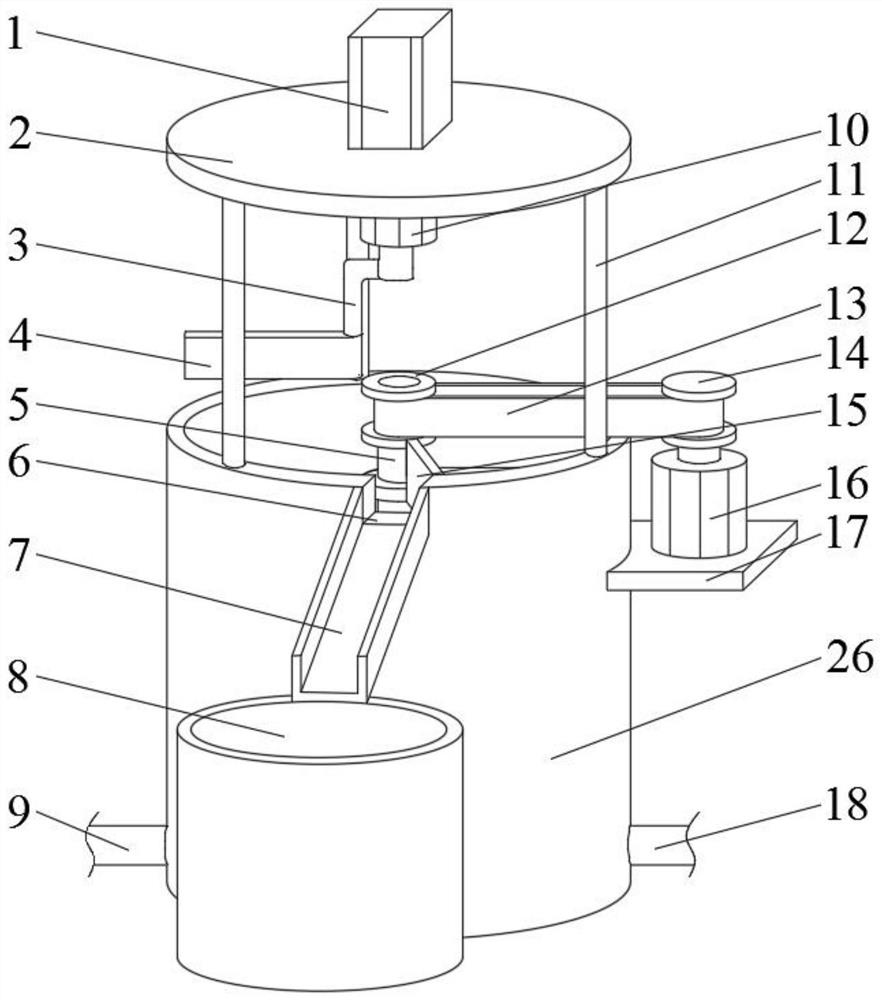
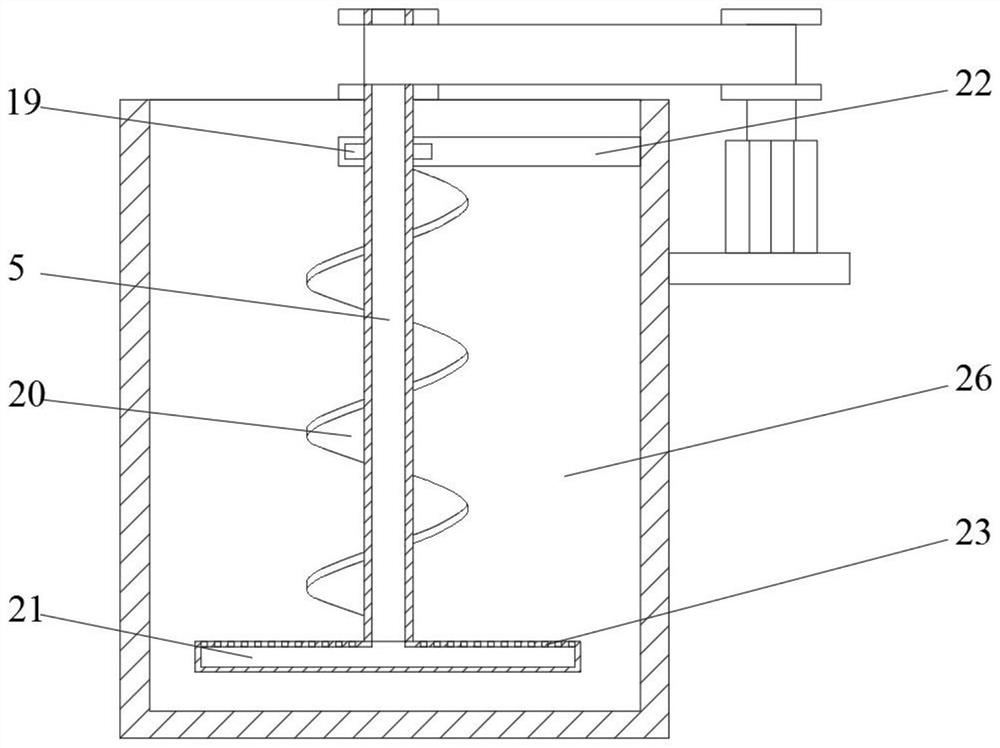
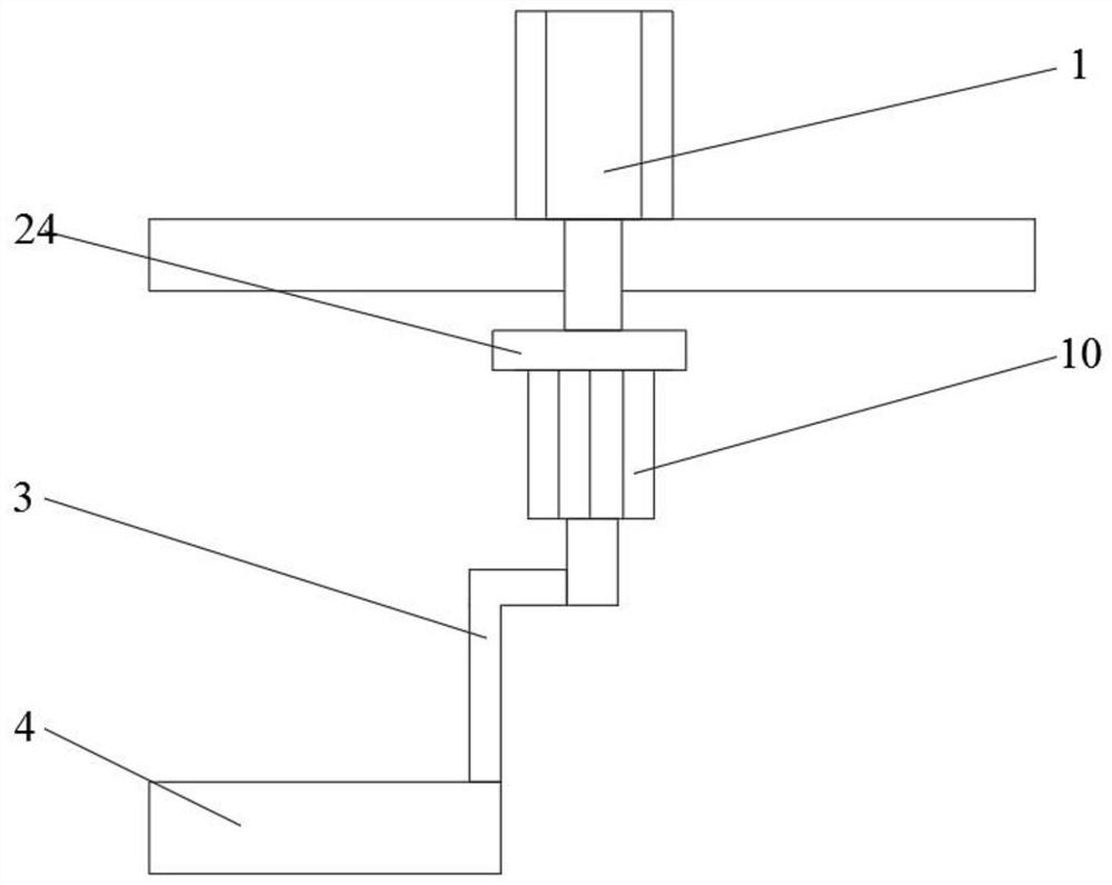
[0029] refer to Figure 1-4 , an oil-water separation device based on the air flotation method, including a separation barrel 26, an oil storage barrel 8 and a top plate 2, an electric telescopic rod 1 is vertically installed at the center of the top of the top plate 2, and the telescopic end of the electric telescopic rod 1 runs through the top plate 2 And with the top plate 2 sliding connection, the bottom end of the telescopic end of the electric telescopic rod 1 is equipped with a second mounting plate 24, and the bottom of the second mounting plate 24 is vertically equipped with a positive and negative motor 10, and the output shaft bottom L of the positive and negative motor 10 The oil scraper 4 is welded on the bottom of the L-shaped rod 3 and the L-shaped rod 3. The positive and negative motor 10 can drive the oil scraper 4 to rotate forward and reverse. When scraping oil, it drives the oil scraper 4 to rotate counterclockwise. Drive the oil scraper 4 to rotate clockwi...

Embodiment 2

[0039] refer to Figure 1-3 And 5, a kind of oil-water separation device based on the air flotation method, comprising a separation barrel 26, an oil storage barrel 8 and a top plate 2, the top center of the top plate 2 is vertically equipped with an electric telescopic rod 1, and the telescopic end of the electric telescopic rod 1 runs through The top plate 2 is also slidably connected with the top plate 2, and the bottom end of the telescopic end of the electric telescopic rod 1 is equipped with a second mounting plate 24, and the bottom of the second mounting plate 24 is vertically equipped with a positive and negative motor 10, and the bottom of the output shaft of the positive and negative motor 10 The end L-shaped rod 3, the bottom end of the L-shaped rod 3 is welded with an oil scraper 4, the middle part of the separation barrel 26 is vertically rotated and connected with a rotating shaft 5, and the separation barrel 26 is provided with a rotating mechanism that drives t...


PUM


Abstract

The invention belongs to the technical field of oil-water separation, particularly relates to an oil-water separation device based on an air floatation method, and provides the following scheme aimingat the problem of incomplete oil-water separation. The device comprises a separation barrel, an oil storage barrel and a top plate,an electric telescopic rod is installed vertically at the top centerof the top plate, a second mounting plate is mounted at the bottom end of the telescopic end of the electric telescopic rod, a forward and reverse motor is vertically mounted at the bottom of the second mounting plate, an L-shaped rod is arranged at the bottom end of an output shaft of the forward and reverse motor, an oil scraping plate is welded to the bottom end of the L-shaped rod, a rotatingshaft is rotatably connected to the middle of the separation barrel, a rotating mechanism is arranged on the separation barrel, an oil outlet is formed in one side of the edge of the top of the separation barrel, a baffle is welded to the side, located at the oil outlet, of the inner wall of the separation barrel, and a stirring mechanism is arranged on the rotating shaft. According to the invention, oil is fully combined with bubbles, complete oil-water separation is ensured, and part of floating foam is prevented from floating on the surface of liquid, so that the floating foam is completely removed.

Description

technical field [0001] The invention relates to the technical field of oil-water separation, in particular to an oil-water separation device based on an air flotation method. Background technique [0002] As we all know, after the food waste is treated with solid-liquid separation technology, the solid food waste will be collected through fermentation and drying, while the separated liquid food waste still contains a certain amount of waste oil, which cannot be directly discharged, and further research is required. deal with. Therefore, an oil-water separation device is needed to separate oil and water, and there are many types of oil-water separation devices, one of which is an oil-water separation device based on air flotation. The air flotation method refers to the use of highly dispersed micro-bubbles as a carrier to adhere to the pollutants in the wastewater, making their buoyancy greater than gravity and buoyancy resistance, so that the pollutants float to the water s...

Claims


Application Information

Patent Timeline
Patent Type & Authority Applications(China)
IPC IPC(8): B01D17/035
CPCB01D17/0205
Inventor 赵洪启戴文强韩海燕吕英东徐军
Owner WUXI HI TECH ENVIRONMENTAL PROTECTION EQUIP TECH
Learn More