
A motor assembly system

A technology for assembling systems and motors, applied in the direction of electromechanical devices, electric components, manufacturing motor generators, etc., can solve the problems of capital consumption, falling off, motor damage, etc., and achieve the effect of reducing capital consumption, reducing matching, and reducing transshipment

Active Publication Date: 2021-09-03
SHANGHAI WEIKEN ELECTRICAL & MECHANICAL ENG CO LTD
View PDF1 Cites 0 Cited by
  • Summary
  • Abstract
  • Description
  • Claims
  • Application Information

AI Technical Summary

Problems solved by technology

[0003] For example, a motor assembly system disclosed by the authorized announcement number CN107453559A, although it realizes the corresponding assembly through the coil and the lower reed assembly section, the motor base and the terminal assembly section, the motor casing, the upper reed piece and the magnet assembly section respectively The semi-finished products of the motor are assembled correspondingly through the first assembly section and the second assembly section to form a finished motor, which reduces manual participation, has a high degree of automation, and improves assembly efficiency and assembly quality, but does not solve the problem of the existing assembly line Long, resulting in some parts of the motor being assembled, it is easy to fall off during transportation, and the long assembly line will cause a lot of capital consumption, and inconvenience to fix and clamp the motor, and the clamping device is relatively simple, and the adjustment mechanism is inconvenient and fine-tuning, it is easy to cause damage to the motor, so we propose a motor assembly system

Method used


Image

  • A motor assembly system
  • A motor assembly system
  • A motor assembly system

Examples


Embodiment Construction

[0022] The following will clearly and completely describe the technical solutions in the embodiments of the present invention with reference to the accompanying drawings in the embodiments of the present invention. Obviously, the described embodiments are only some, not all, embodiments of the present invention. Based on the embodiments of the present invention, all other embodiments obtained by persons of ordinary skill in the art without making creative efforts belong to the protection scope of the present invention.

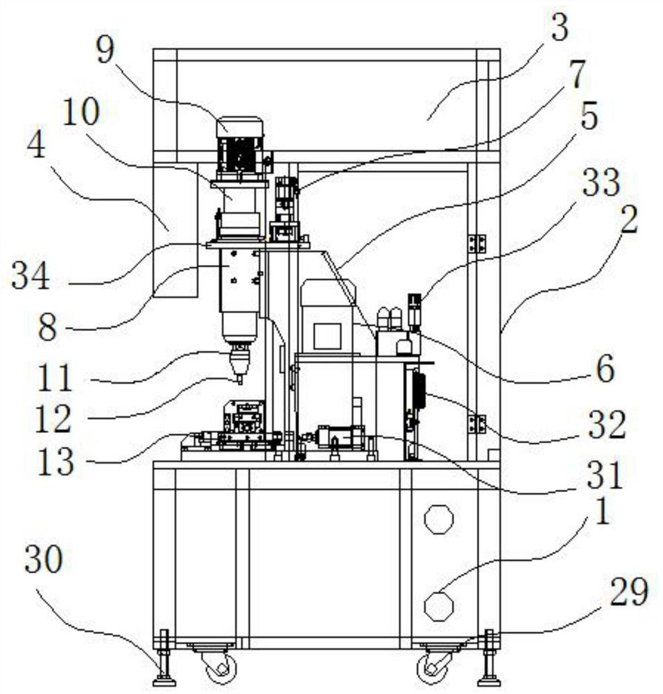
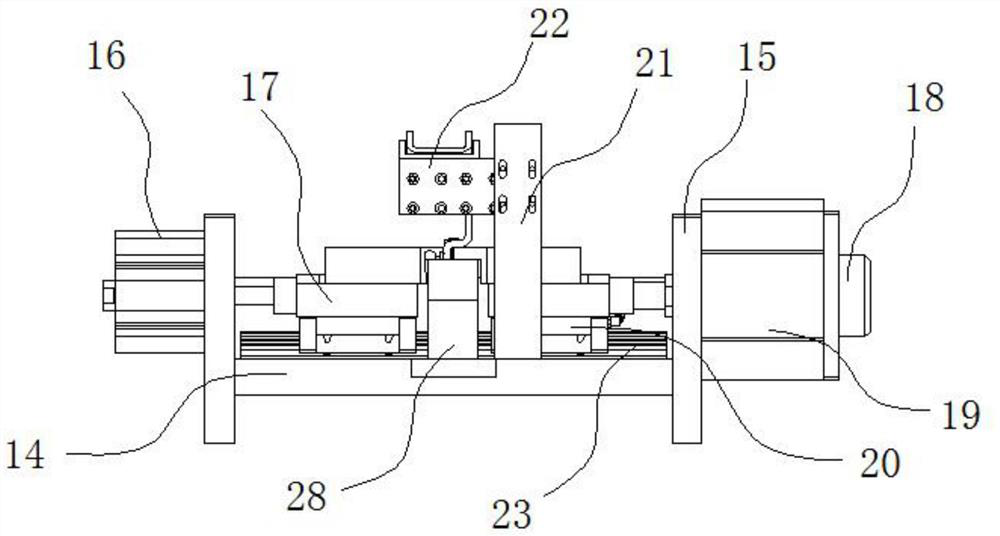
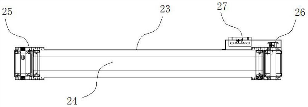
[0023] see Figure 1-Figure 3 , the present invention provides a technical solution: a motor assembly system, including an assembly cabinet 1, the rear side of the assembly cabinet 1 is fixed with a back plate 2, the top of the back plate 2 is welded with a top plate 3, and the top and bottom of the top plate 3 are fixed and installed There is a PLC control machine 4, a fixed plate 5 is fixedly installed on the upper part of the assembly cabinet 1, an adjustin...


PUM


Abstract

The invention discloses a motor assembly system; comprising an assembly cabinet, the assembly cabinet is connected with a top plate through a back plate, a fixing plate is installed on the upper part of the assembly cabinet, and an adjusting electric cylinder and a fine-tuning electric cylinder are installed inside the fixing plate. Cylinder, the front end of the top plate is equipped with a motor, the output end of the motor is connected with a movable connection shaft, and the front part of the upper end of the assembled cabinet is equipped with a clamping mechanism, and the clamping mechanism includes a mounting plate, a first clamping electric cylinder, the first clamping block, the second clamping electric cylinder and the second clamping block, the upper part of the mounting plate is equipped with a slide rail, and the measuring end of the slide rail is equipped with the first installation head and the second Installation head; the assembly line equipment of the present invention is combined on the assembly cabinet, reducing the consumption of funds and personnel, and reducing the transportation of motor assembly. A clamping mechanism is provided for stable clamping and fixing, preventing parts from shaking and falling off, and fine-tuning the electric cylinder Can protect the motor.

Description

technical field [0001] The invention belongs to the technical field of auto parts processing, and in particular relates to a motor assembly system. Background technique [0002] A motor is an electric motor or an engine. The working principle is that the energized coil is forced to rotate in the magnetic field to drive the starter rotor to rotate, and the pinion on the rotor drives the engine flywheel to rotate. The motor consists of an internal ring gear and a matching gear or rotor. The inner ring gear and the housing can be fixedly connected together, and the oil entering from the oil port pushes the rotor to revolve around a center point. This slowly rotating rotor drives the output through a splined shaft to become a cycloid hydraulic motor. After the first cycloidal motor came out, after decades of evolution, another concept motor began to take shape. This kind of motor has rollers installed in the built-in ring gear. The motor with rollers can provide high startin...

Claims


Application Information

Patent Timeline
Patent Type & Authority Patents(China)
IPC IPC(8): H02K15/00H02K15/14
CPCH02K15/00H02K15/14
Inventor 郑春虎
Owner SHANGHAI WEIKEN ELECTRICAL & MECHANICAL ENG CO LTD
Learn More