
Dewatering and drying device for sludge treatment

A drying device and sludge treatment technology, applied in the direction of sludge drying, heating devices, drying solid materials, etc., can solve the problems of uneven heating of sludge, reduce drying effect, affect dehydration effect, etc., to increase practical performance and application flexibility, ensuring efficiency and quality, and increasing efficiency

Inactive Publication Date: 2021-01-29
熊权威
View PDF1 Cites 0 Cited by
  • Summary
  • Abstract
  • Description
  • Claims
  • Application Information

AI Technical Summary

Problems solved by technology

[0003] According to the publication number: "CN210885747U" "a dehydration device for sludge treatment", the sludge is transported through two conveying structures, and a heating wire is connected under each conveying structure, and the heating wire is used on the conveying structure. The sludge is heated and dehydrated, but the dehydration efficiency is low only through the heating wire, and the sludge is always in a moving state, which will lead to uneven heating of the sludge, which will directly affect the dehydration effect, and the heating wire is not directly in contact with the sludge. The medium conducts heat transfer, which causes heat loss, further reducing the drying effect

Method used


Image

  • Dewatering and drying device for sludge treatment
  • Dewatering and drying device for sludge treatment
  • Dewatering and drying device for sludge treatment

Examples


Embodiment Construction

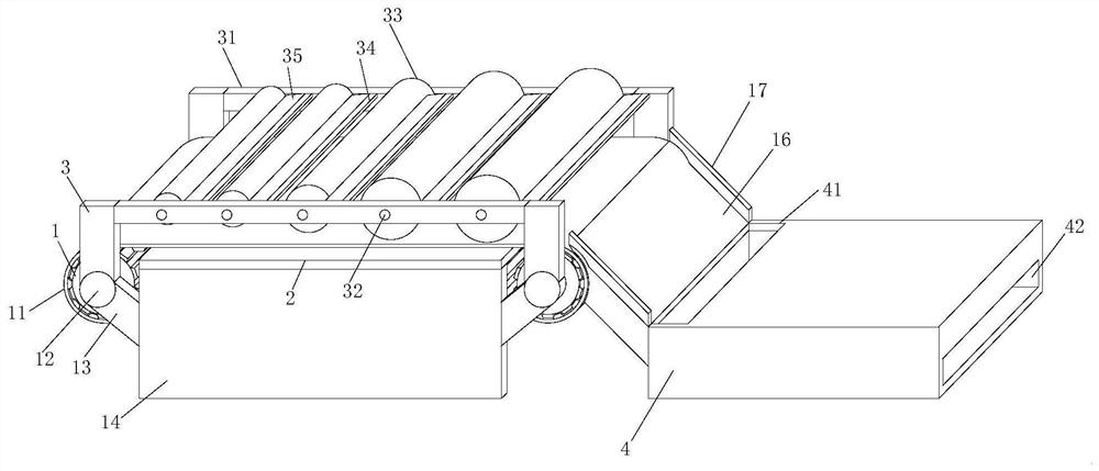
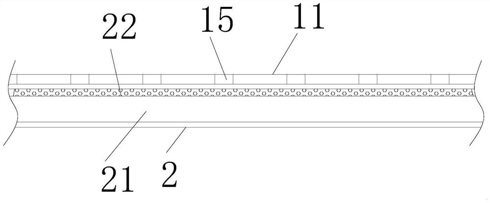
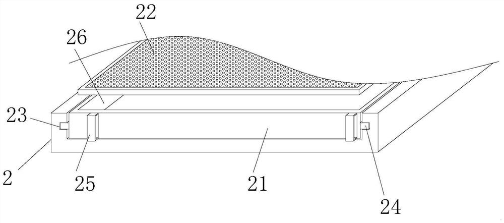
[0027] Such as Figure 1-6 As shown, this specific embodiment adopts the following technical solutions: a dehydration and drying device for sludge treatment, including a conveyor belt 1, a support plate 14 is set up on both sides of the middle of the conveyor belt 1, and a storage platform 2 is connected to the top of the support plate 14, One end of the conveyor belt 1 is provided with a dryer 4, the inside of the dryer 4 is connected with a baking plate 462, and a plurality of pressing rollers 33 are provided above the conveyor belt 1;

[0028] There are multiple pressing rollers 33, and the two ends of each pressing roller 33 are fixedly connected with a rotating shaft 32, and the rotating shaft 32 is rotatably connected with a crossbeam 31. One side of each pressing roller 33 is equipped with a scraper 35, and the scraper 35 One end is fixedly connected with a fixed plate 34, and the fixed plate 34 is fixedly connected to the opposite side walls of the two beams 31 through...


PUM


Abstract

The invention discloses a dewatering and drying device for sludge treatment. The dewatering and drying device comprises a conveying belt; supporting plates are arranged on the two sides of the middleof the conveying belt; a storage platform is connected to the top ends of the supporting plates; a drying machine is arranged at one end of the conveying belt; a baking plate is connected to the interior of the drying machine; and a plurality of pressing rollers are arranged above the conveying belt. The dewatering and drying device for the sludge treatment provided by the invention has the following beneficial effects: the sludge on the conveying belt is baked through an electric heating pipe, residual water in the sludge is rapidly evaporated, the sludge becomes dry and is finally dischargedthrough a discharging port, telescopic rods are detachably connected to the positions, close to the edges of the two ends, of the top of the baking plate, and lifting of the baking plate is controlled through the telescopic rods, thus flexible adjustment can be conducted according to the actual situation, the practical performance and the application flexibility are improved, through conveying ofthe conveying belt and blocking of a leveling plate, sedimentation accumulated on the conveying belt can be leveled, drying is facilitated, sludge is heated more evenly, and the drying efficiency isimproved.

Description

Technical field: [0001] The invention belongs to the technical field of sludge treatment and drying equipment, in particular to a dehydration and drying device for sludge treatment. Background technique: [0002] Sludge treatment is one of the means of environmental governance. By purifying the silt, the treated soil can be buried in some needed places, and even can be filled with soil to make fields. Through the treatment of silt, it can be greatly improved. Increase the intensity of environmental improvement to a certain extent. [0003] According to the publication number: "CN210885747U" "a dehydration device for sludge treatment", the sludge is transported through two conveying structures, and a heating wire is connected under each conveying structure, and the heating wire is used on the conveying structure. The sludge is heated and dehydrated, but the dehydration efficiency is low only through the heating wire, and the sludge is always in a moving state, which will lea...

Claims


Application Information

Patent Timeline
IPC IPC(8): F26B17/04F26B5/14F26B23/04F26B25/02
CPCF26B5/14F26B17/04F26B23/04F26B25/02F26B2200/18
Inventor 熊权威
Owner 熊权威
Learn More