
Combustion chamber burner structure with heating system and operation method

A heating system and combustion chamber technology, which is applied in the coking field, can solve the problems of low temperature, large heat dissipation in the vertical fire channel of the burner, decrease in the strength of coke at the burner, etc., and achieves the effects of easy operation, saving resources and reducing the cost of coking.

Inactive Publication Date: 2021-01-29
ANGANG STEEL CO LTD
View PDF3 Cites 0 Cited by
  • Summary
  • Abstract
  • Description
  • Claims
  • Application Information

AI Technical Summary

Problems solved by technology

[0007] Aiming at the problems of high heat dissipation and low temperature in the furnace head of the coke oven combustion chamber, and the decrease of coke strength at the furnace head of the carbonization chamber, the present invention proposes a structure and operation method of the furnace head of the combustion chamber with a heating system. The high-temperature flue gas discharged from the fire channel supplements the furnace vertical fire channel. This process is simple to operate and easy to realize. It can quantitatively adjust the temperature at the furnace vertical fire channel, improve the quality of coke at the furnace head, save resources and reduce coking costs.

Method used


Image

  • Combustion chamber burner structure with heating system and operation method
  • Combustion chamber burner structure with heating system and operation method
  • Combustion chamber burner structure with heating system and operation method

Examples


Embodiment Construction

[0026] The structure and operation method of a combustion chamber burner with a heating system according to the present invention will be described in detail below in conjunction with the accompanying drawings. The protection scope of the present invention is not limited to the following embodiments, which are listed for illustrative purposes only and do not limit the present invention in any way.

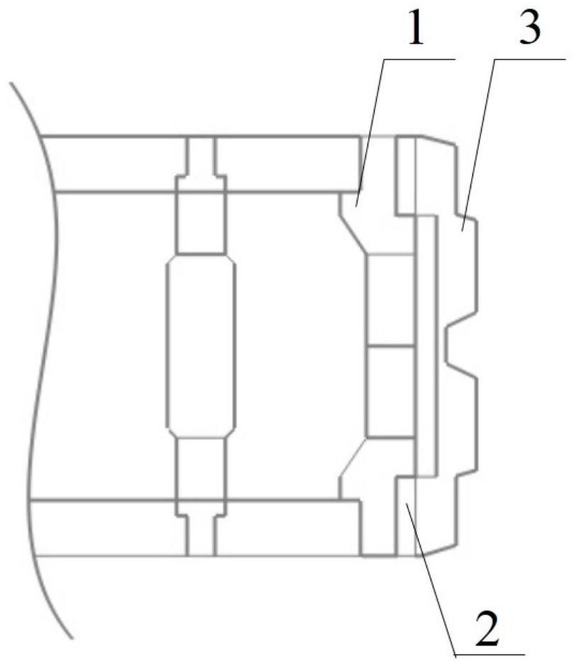
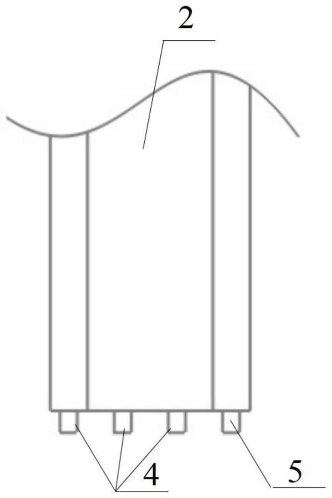
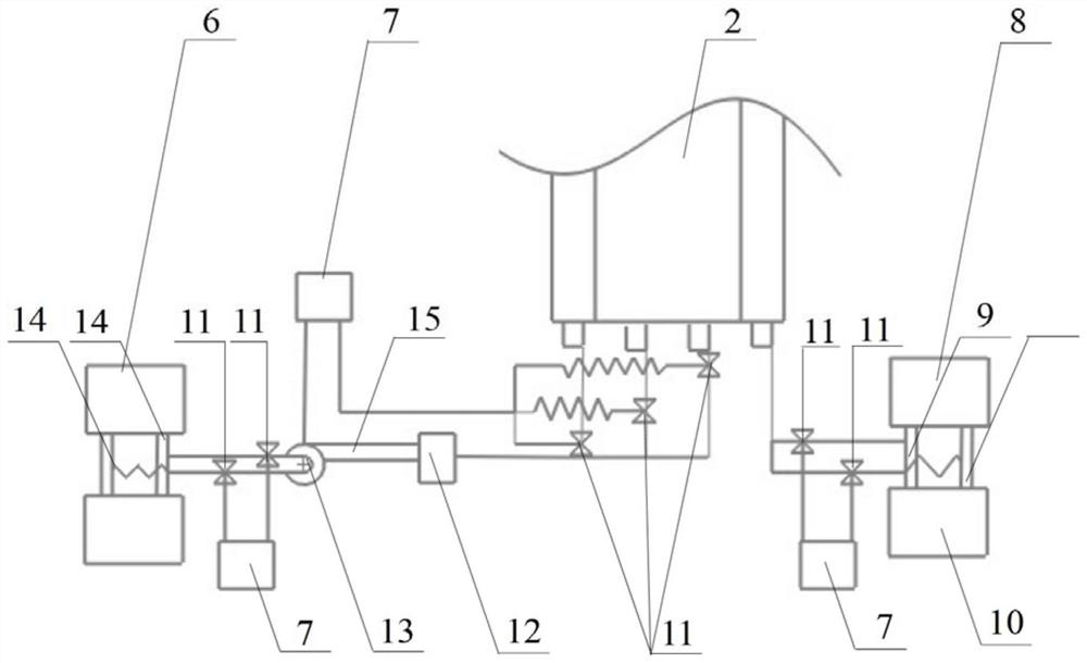
[0027] A combustion chamber furnace head structure with a heating system is characterized in that: a heating system is installed on the machine side and / or the coke side of the coke oven combustion chamber, the heating system includes a metal hollow plate 2, and the metal hollow plate 2 is set Between the inner refractory brick 1 and the outer refractory brick 3 of the furnace head masonry, the metal hollow plate 2 is connected to the inner refractory brick 1 and the inner side of the outer refractory brick 3 is the same, and the metal hollow plate 2 and the inner refractory brick 3...


PUM

PropertyMeasurementUnit
thicknessaaaaaaaaaa

Abstract

The invention discloses a combustion chamber burner structure with a heating system and an operation method. The heating system is arranged on the machine side and / or the coke side of a coke oven combustion chamber, the heating system comprises a metal hollow plate, the metal hollow plate is arranged between inner-layer refractory bricks and outer-layer refractory bricks of a burner brickwork, theside, which is connected with the inner-layer refractory bricks, of the metal hollow plate is the same as the inner sides of the outer-layer refractory bricks, the side, which is connected with the outer-layer refractory bricks, of the metal hollow plate is the same as the outer sides of the inner-layer refractory bricks, a smoke inlet and a smoke outlet are formed below the metal hollow plate, the smoke inlet is connected with a chute below a middle vertical flame path through a smoke pipeline, and the smoke outlet is connected with a chute below the burner vertical flame path. The problem of low temperature of the vertical flame path of the combustion chamber burner of the coke oven is solved, and the coke quality of the burner is improved. The process is simple and convenient to operate and easy to implement, and resources are saved. The temperature of the coke cake in a carbonization chamber of the burner of the coke oven can be increased to 950-1050 DEG C, and the strength of thecoke after reaction is increased to 68.1% from 66.3%.

Description

technical field [0001] The invention belongs to the field of coking, and relates to a technology for increasing the temperature of a burner head of a coke oven combustion chamber, in particular to a structure and an operation method of a burner head of a combustion chamber with a heating system. Background technique [0002] At present, the coke oven combustion chambers of coking plants of most domestic iron and steel complexes use blast furnace gas and air to preheat and burn, and transfer the heat to the carbonization chamber through the partition wall for high-temperature carbonization of pulverized coal. Because there are few combustible components in the blast furnace gas, the calorific value is low, and the heat dissipation of the combustion chamber burner vertical flue is large, resulting in low temperature of the combustion chamber burner vertical flue. During the coking time, the coke at the furnace head of the carbonization chamber is not fully mature, resulting in...

Claims


Application Information

Patent Timeline
Patent Type & Authority Applications(China)
IPC IPC(8): C10B21/10
CPCC10B21/10
Inventor 刘福军庞克亮王超武吉
Owner ANGANG STEEL CO LTD
Learn More