
Filling head for liquid filling machine

A filling machine and filling head technology, applied in liquid bottling, liquid processing, packaging, etc., can solve problems such as pollution of equipment and material waste, and achieve the effect of reducing material waste

Inactive Publication Date: 2021-01-29
ZHANGJIAGANG WANJIN MACHINERY CO LTD
View PDF5 Cites 1 Cited by
  • Summary
  • Abstract
  • Description
  • Claims
  • Application Information

AI Technical Summary

Problems solved by technology

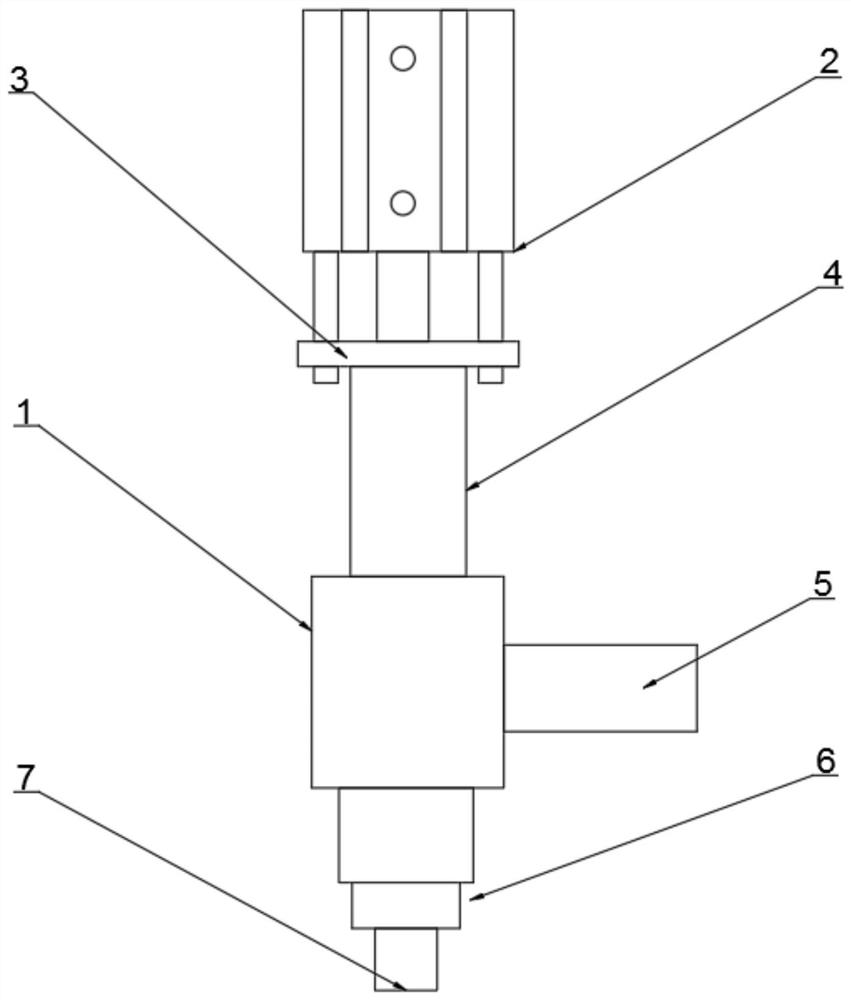
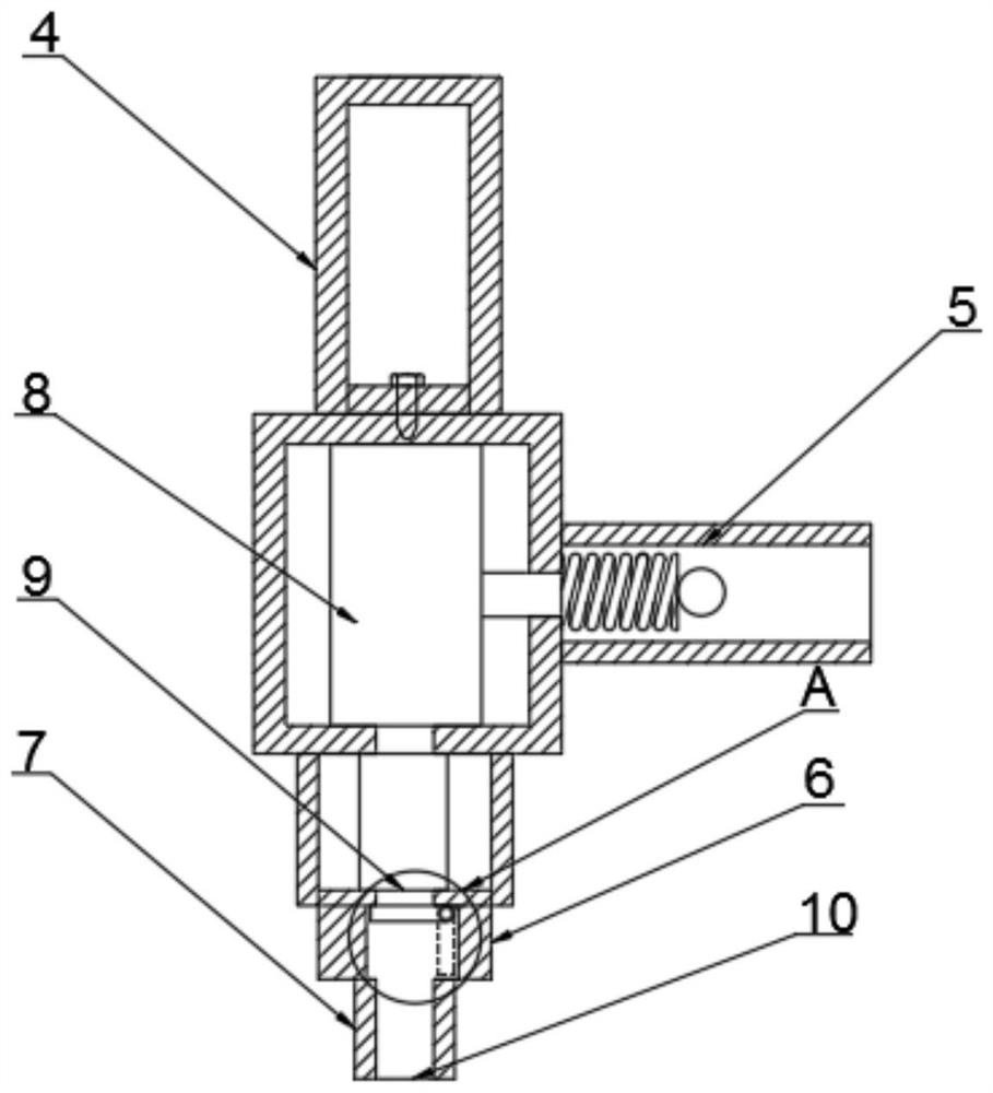
[0004] The purpose of the present invention is to provide a filling head for a liquid filling machine to solve the problem of dripping residual material and forming liquid leakage in the above background technology, which not only causes waste of materials but also pollutes equipment

Method used


Image

  • Filling head for liquid filling machine
  • Filling head for liquid filling machine
  • Filling head for liquid filling machine

Examples


Embodiment Construction

[0018] The following will clearly and completely describe the technical solutions in the embodiments of the present invention with reference to the accompanying drawings in the embodiments of the present invention. Obviously, the described embodiments are only some, not all, embodiments of the present invention. Based on the embodiments of the present invention, all other embodiments obtained by persons of ordinary skill in the art without making creative efforts belong to the protection scope of the present invention.

[0019] In the description of the present invention, it should be noted that the terms "center", "upper", "lower", "left", "right", "front", "rear", "vertical", "horizontal", The orientation or positional relationship indicated by "inner", "outer", etc. is based on the orientation or positional relationship shown in the drawings, and is only for the convenience of describing the present invention and simplifying the description, rather than indicating or implyin...


PUM


Abstract

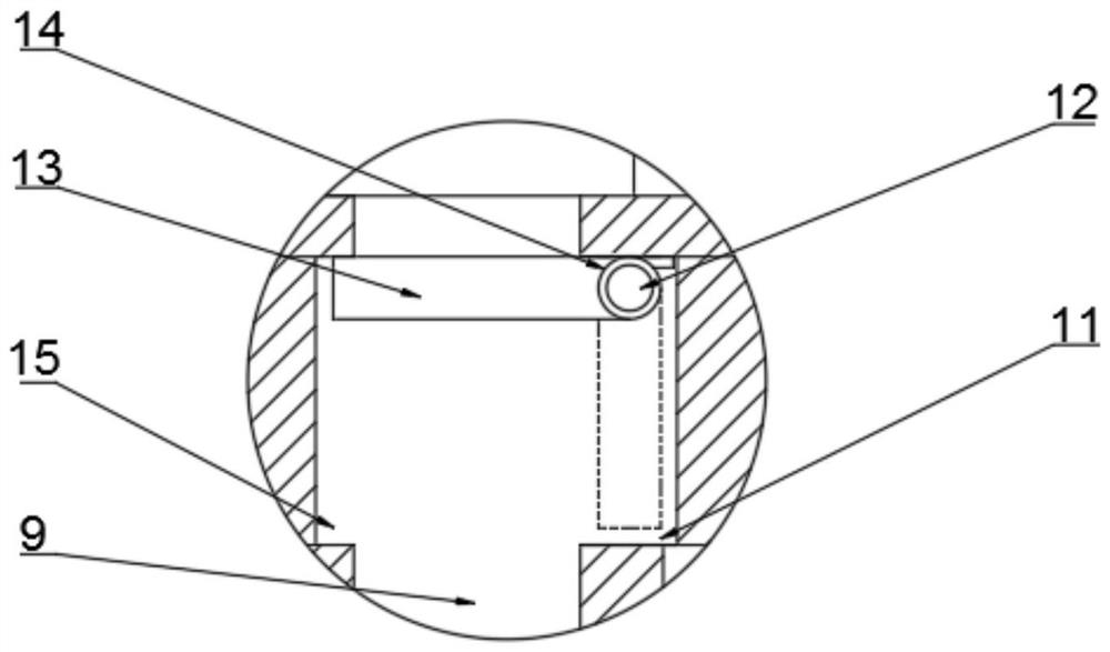
The invention discloses a filling head for a liquid filling machine. The machine comprises a main body, an air cylinder and a filling needle cylinder. A connector is arranged at the upper end of the main body, the bottom end of the air cylinder is in threaded connection with a connecting flange, a water inlet pipe is arranged on one side of the main body, and a connecting block is arranged at thebottom end of the main body. A placing groove is formed in one side of the interior of the connecting block, and a limiting groove is formed in the other side. A rotating shaft is arranged at the topend of the placing groove, a leakage-proof plate is rotatably connected to the surface of the rotating shaft, and torsional springs are arranged in the middles of the surfaces of the rotating shaft and the leakage-proof plate. According to the filling head for the liquid filling machine, the main body is connected with the filling needle cylinder through the connecting block, when the filling headstops working at the moment a filling bottle body is filled up, the leakage-proof plate rotates upwards under the action of elastic force of the torsional spring, the top end of a limiting groove isclamped by a floor, a filling channel is closed, and residual liquid is prevented from dripping when filling is stopped, so that material waste is reduced, and equipment is protected from being polluted by the residual liquid.

Description

technical field [0001] The invention relates to the technical field of filling machines, in particular to a filling head for a liquid filling machine. Background technique [0002] Filling machines are mainly a small category of products in packaging machines. From the perspective of packaging materials, they can be divided into liquid filling machines, paste filling machines, powder filling machines, and particle filling machines; from the degree of automation of production It is divided into semi-automatic filling machine and fully automatic filling production line. Recently, with the QS certification of food, edible oil manufacturers have begun to pay attention to product quality and packaging, so the oil filling machine has a prominent position in the filling machine. [0003] After the filling head of the existing filling machine finishes filling the material, there will still be some residual material dripping down, forming liquid leakage, which not only causes materi...

Claims


Application Information

Patent Timeline
Patent Type & Authority Applications(China)
IPC IPC(8): B67C3/26
CPCB67C3/26B67C3/2608
Inventor 秦志洪
Owner ZHANGJIAGANG WANJIN MACHINERY CO LTD
Learn More