Automobile blind area detection alarm method and system

A blind spot, automobile technology, applied in signal devices and other directions, can solve the problems of many interference targets, difficult to achieve ideal ranging, speed and angular resolution, accuracy, high false alarm rate, etc., to reduce interference and improve environmental adaptability. performance effect

Active Publication Date: 2021-01-29
CHONGQING CHANGAN AUTOMOBILE CO LTD
View PDF22 Cites 1 Cited by
  • Summary
  • Abstract
  • Description
  • Claims
  • Application Information

AI Technical Summary

Problems solved by technology

[0004]1) The viewing angle of the millimeter-wave radar is getting wider and wider, and the detection area of ​​the millimeter-wave radar is getting bigger and bigger. The millimeter-wave radar detects There are more interference targets on both sides of the car body, and the time is longer, and the millimeter-wave radar is affected and limited by its own hardware parameter performance, especially at a low cost, it is difficult to achieve ideal ranging, speed and angle resolution and accuracy
[0005]2) After the SNR detection and the commonly used Constant False Alarm Rate (CFAR, Constant False-Alarm Rate) detection completely eliminate the environmental interference, it will Missing alarms occur; this method is difficult to eliminate interference targets with the same true value attribute, and it is inevitable that there is still a high false alarm rate in the face of strong interference
[0006]3) Through the spectrum envelope and signal-to-noise (miscellaneous) ratio, the method of establishing a target in a single frame and confirming an alarm in multiple frames can be improved to a certain extent under normal conditions. Blind zone alarm accuracy, but when dealing with complex road conditions (such as multi-path reflections, curve scenes, irregular guardrails, fences, street light poles), it is still difficult to solve the threshold crossing of true and false targets on each judgment attribute

Method used


Image

  • Automobile blind area detection alarm method and system
  • Automobile blind area detection alarm method and system
  • Automobile blind area detection alarm method and system

Examples


Embodiment Construction

[0032] Such as Figure 4 The vehicle blind spot detection and alarm method shown is executed by the controller, and the controller obtains the signals needed in the method from the CAN bus. The blind spot detection and warning method includes:

[0033]Step 1. The controller judges the driving mode of the vehicle according to the vehicle speed Vo, the steering wheel angle, and the yaw rate. If any of the conditions a~f is met, the controller judges that the vehicle is turning, otherwise it judges that the vehicle is traveling straight, and then executes step two. Among them, condition a is: the yaw rate is greater than 0.04° / s; condition b is: 0100 km / h, and the steering wheel rotation angle is greater than or equal to 8°.

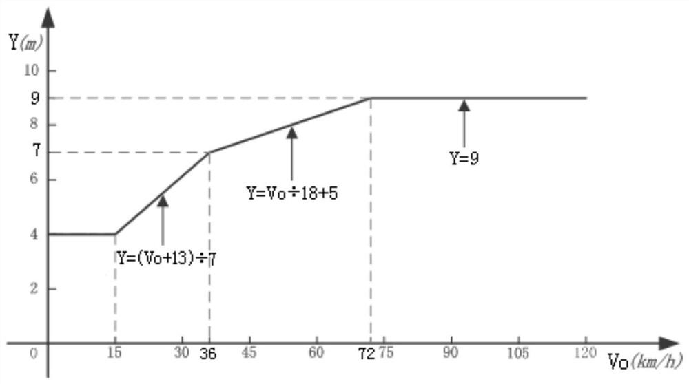
[0034] Step 2: The controller determines the alarm area according to the driving mode of the vehicle and the speed Vo of the vehicle. If the vehicle is traveling straight, the alarm area is determined to be surrounded by points A, B, E, D, and C in sequenc...


PUM


Abstract

The invention discloses an automobile blind area detection alarm method and system. The method comprises steps of S1, judging an automobile driving mode according to the speed Vo, steering wheel angleand yaw velocity of an automobile, and then executing S2; S2, determining an alarm area according to the vehicle driving mode and the vehicle driving speed Vo, and then executing S3; S3, judging whether a target enters an alarm area or not, if so, executing the step S4, and otherwise, ending; S4, judging whether the target has a historical tracking track or not, if so, executing the step S6, andotherwise, executing the step S5; S5, judging whether the target meets a secondary screening condition or not, if so, executing the step S6, and otherwise, returning to execute the step S3; S6, judging whether the duration time of the target in the alarm area exceeds a preset first time threshold value or not, if so, performing target alarm, and then ending, otherwise, returning to execute S3. According to the method, the false alarm rate under the environment where false alarm is easy to occur, such as static guardrails and enclosing walls, can be reduced.

Description

technical field [0001] The invention belongs to the field of automobile electrical appliances, and in particular relates to a method and system for detecting and alarming an automobile blind spot. Background technique [0002] In the context of automobile intelligence, the current intelligent driving assistance system based on millimeter-wave radar has been widely used in various car models of major brand manufacturers, and the penetration rate has increased significantly. Automobile users are more and more interested in intelligent driving assistance. Interested, began to know more, more demanding. As one of the intelligent driving assistance systems, the blind spot detection and alarm system has become the standard configuration of mid-to-high-end models and even high-end models of passenger cars. With the widespread application of blind spot detection and alarm systems, the complex and diverse driving environments they face bring challenges to the ability to adapt to the...

Claims


Application Information

Patent Timeline
IPC IPC(8): B60Q9/00
CPCB60Q9/008
Inventor 袁松
Owner CHONGQING CHANGAN AUTOMOBILE CO LTD
Why Eureka
Try Eureka