
Extrusion forming equipment for PVC pipe production

A PVC pipe, extrusion molding technology, applied in the field of extrusion molding equipment for PVC pipe production, can solve the problems of corrugated PVC plastic pipe surface convex defects, etc., to achieve the effect of avoiding difficult removal

Inactive Publication Date: 2021-01-29
北京林远商贸有限公司
View PDF0 Cites 6 Cited by
  • Summary
  • Abstract
  • Description
  • Claims
  • Application Information

AI Technical Summary

Problems solved by technology

[0003] Due to the fast solidification speed of PVC plastic, after the extruder for PVC pipe production finishes extruding the corrugated PVC pipe, the residual PVC plastic at the rear end will squeeze into the concave surface of the inner wall of the forming head and quickly dry and solidify If you continue to add PVC plastic raw materials for extrusion molding at this time, it is easy to appear that the convex surface of the extruded corrugated PVC plastic pipe is incomplete.

Method used


Image

  • Extrusion forming equipment for PVC pipe production
  • Extrusion forming equipment for PVC pipe production
  • Extrusion forming equipment for PVC pipe production

Examples


Embodiment 1

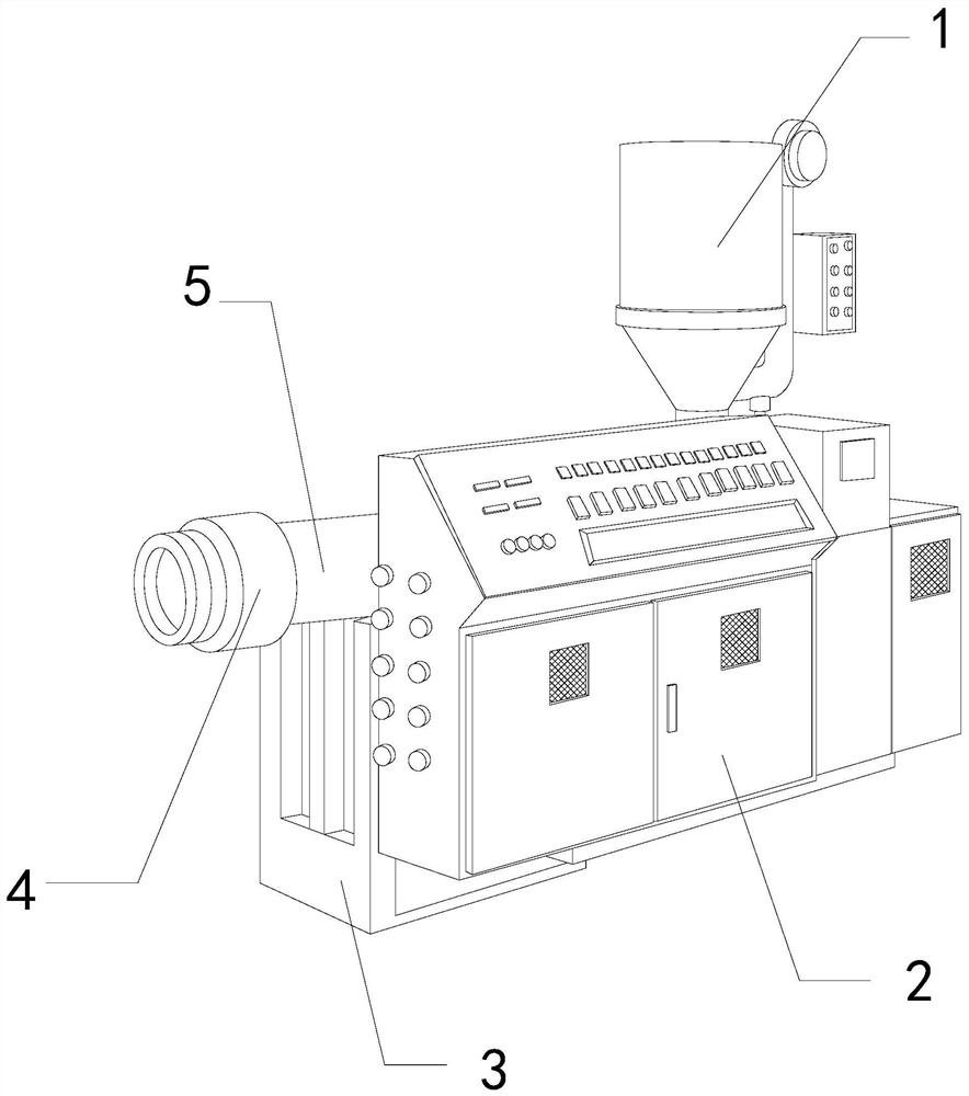
[0026] For example figure 1 -example Figure 5 Shown:

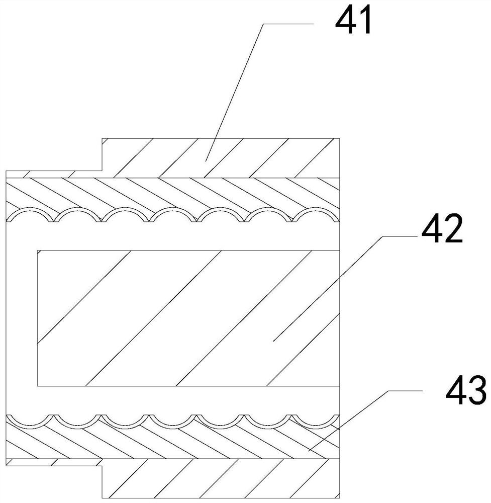
[0027] The present invention provides an extrusion molding equipment for PVC pipe production, the structure of which includes a heating bucket 1, a machine body 2, a support 3, a forming head 4, and an extrusion tube 5. The heating bucket 1 is embedded in the extrusion tube 5. At the upper end position, the body 2 is welded to the support 3, the extrusion tube 5 is embedded and connected to the body 2, the forming head 4 and the extrusion tube 5 are an integrated structure; the forming head 4 includes an outer frame 41. The middle solid block 42 and the inner frame 43. The middle solid block 42 and the outer frame 41 are an integrated structure, and the inner frame 43 is embedded and fixed at the inner side of the outer frame 41.

[0028] Wherein, the inner frame 43 includes connecting plate a1, telescopic block a2, lower connecting plate a3, and elastic sheet a4, the telescopic block a2 fits with the bottom of the conn...

Embodiment 2

[0034] For example Figure 6 -example Figure 8 Shown:

[0035] Wherein, the central solid block 42 includes a shrinkage plate c1, a receiving plate c2, a rebound strip c3, and a front plate c4, the shrinkage plate c1 is movably engaged with the receiving plate c2, and the complex elastic strip c3 is installed on the receiving plate Between c2 and the contraction plate c1, the front plate c4 and the receiving plate c2 are of an integrated structure. The extrusion of the plastic to the shrink board c1 can make the shrink board c1 shrink inwardly.

[0036] Wherein, the front plate c4 includes a combination plate c41, an air guide cavity c42, and an overhanging block c43. Together, there are six stretching blocks c43, which are evenly distributed in parallel at the front end of the connecting plate c41, and the extruding airflow inside the object can push the stretching blocks c43 to protrude forward.

[0037] Wherein, the extension block c43 includes a plate d1, an extension p...


PUM


Abstract

The invention discloses extrusion forming equipment PVC pipe production. The extrusion forming equipment structurally comprises a heating hopper, a machine body, a support seat, a forming head and anextrusion pipe, and the heating hopper is fixedly embedded at the upper end of the extrusion pipe; the machine body is welded on the support seta, and the extrusion pipe is fixedly embedded in the machine body; and the forming head and the extrusion pipe are of an integrated structure. Upon completion of extrusion of PVC plastic, a telescopic block can be quickly pushed to slide downwards throughan elastic piece, so that a lower swing plate can be quickly swung downwards along a plate body; thus, the PVC plastic at the bottom of a lower connecting plate can be loosened, and bounced off downwards through the lower swing plate; and an extending block can be pushed to extend forwards along a combining plate through airflow in an air guide cavity. When a contraction plate loses extrusion of molten PVC plastic, the contraction plate can be pushed to reset upwards through a rebounding strip, so that the extending block can be attracted by reverse airflow to slide backwards; and thus, a PVCplastic layer on the outer surface of a front plate can fall off easily.

Description

technical field [0001] The invention relates to the field of PVC, in particular to extrusion molding equipment for PVC pipe production. Background technique [0002] The extruder for PVC pipe production is mainly used to extrude PVC plastic into pipes. The PVC plastic is melted into molten PVC plastic at high temperature through the heating bucket, and then the molten PVC plastic is extruded through the extrusion rod. The forming head of the solid column provided in the middle extrudes the molten PVC plastic into PVC pipe products, which is a common equipment in the PVC pipe production industry. Based on the above description, the inventors found that an existing extrusion molding equipment for PVC pipe production There are mainly the following deficiencies, for example: [0003] Due to the fast solidification speed of PVC plastic, after the extruder for PVC pipe production finishes extruding the corrugated PVC pipe, the residual PVC plastic at the rear end will squeeze int...

Claims


Application Information

Patent Timeline
IPC IPC(8): B29C48/13B29C48/27
CPCB29C48/13B29C48/272
Inventor 李思林
Owner 北京林远商贸有限公司
Learn More