Tubular structure aviation chair back composite material product mold adopting mold pressing process

A technology of tubular structure and composite material, applied in the field of product molds, can solve the problems of easy tilting of inserts, difficult removal of preformed mandrels, product clamping, etc., achieves uniform wall thickness, solves difficulty in taking parts, and has good performance. Effect

Pending Publication Date: 2021-01-29
上海晋飞碳纤科技股份有限公司
View PDF0 Cites 0 Cited by
  • Summary
  • Abstract
  • Description
  • Claims
  • Application Information

AI Technical Summary

Problems solved by technology

[0002] For traditional ordinary molded product molds, the cavity surface of the mold is generally designed and processed as a whole, which will cause product clamping and cannot ensure uniform product wall thickness
The traditional side-drawing slider mold only relies on the guide rail to limit the position. When the insert is opened and drawn to the limit position, the insert is easy to tilt, which poses a safety hazard, and the manual thrust of the composite mold at room temperature is not strong enough to close the mold or wire. A strong lever will increase the inserts and cost
When traditional tubular products are molded with preformed mandrels, they are limited by product structure characteristics. After prepreg wrapping, it is difficult to take out the preformed mandrels. Taking out the mandrels will affect the size of the inner wall of the tubular product.

Method used


Image

  • Tubular structure aviation chair back composite material product mold adopting mold pressing process
  • Tubular structure aviation chair back composite material product mold adopting mold pressing process
  • Tubular structure aviation chair back composite material product mold adopting mold pressing process

Examples


Embodiment Construction

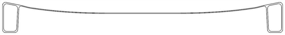
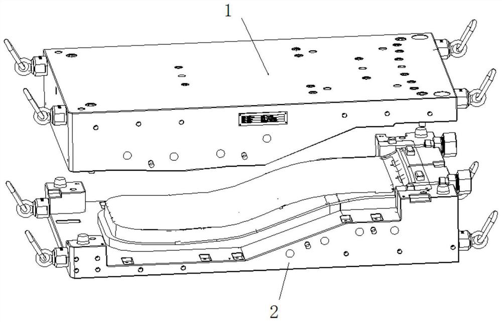
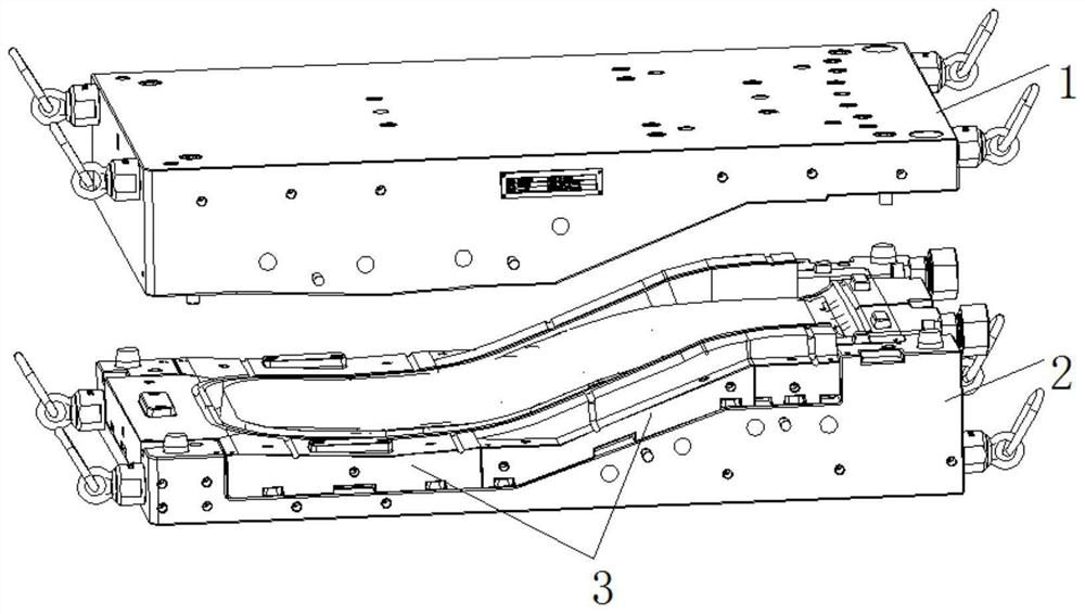
[0028] The preferred embodiments of the present invention are given below in conjunction with the accompanying drawings to describe the technical solution of the present invention in detail. figure 1 Schematic diagram of the structure of the product made for practical use of the present invention. figure 2 It is a schematic diagram of the overall structure of the mold provided by the present invention. image 3 It is a structural schematic diagram of the installation position of the side-drawing slider structure. Figure 4 It is an auxiliary blowing structure in the present invention. As shown in the above figure: the tubular structure aviation seat back composite product mold of the molding process provided by the present invention includes: an upper mold cavity 1, a lower mold cavity 2, a side-drawing slider 3, an auxiliary blowing structure 4; a side-drawing slide The block 3 is located between the upper mold cavity 1 and the lower mold cavity 2, and the auxiliary blowin...


PUM


Abstract

The invention relates to a tubular structure aviation chair back composite material product mold adopting a mold pressing process. The tubular structure aviation chair back composite material productmold comprises an upper mold cavity, a lower mold cavity, a side drawing sliding block and an auxiliary air blowing structure. The side drawing sliding block is located between the upper mold cavity and the lower mold cavity. The auxiliary air blowing structure is installed on the upper mold cavity or the lower mold cavity. A composite material product needing to be formed is located in a cavity formed by the upper mold cavity and the lower mold cavity. According to the tubular structure aviation chair back composite material product mold, the wall thickness of the produced product is ensuredto be uniform, the prepreg interlayer performance is good, and the surface of the product is smooth and free of steps. By means of the side drawing sliding block structure in the tubular structure aviation chair back composite material product mold, the problem that tubular structure material sheets are not easy to lay and paste in a small space is solved, and meanwhile the problem that the product is difficult to take is solved. By means of the auxiliary air blowing structure in the tubular structure aviation chair back composite material product mold, the problem that no pressure exists during the forming of the inner wall of a tubular structure is solved.

Description

technical field [0001] The invention relates to a product mould, in particular to a product mold of tubular structure aviation seat back composite material which ensures uniform wall thickness of the produced product, good interlayer performance of prepreg material, and smooth product surface without steps. Background technique [0002] For traditional ordinary molded product molds, the cavity surface of the mold is generally designed and processed as a whole, which will cause product clamping and cannot ensure uniform product wall thickness. The traditional side-drawing slider mold only relies on the guide rail to limit the position. When the insert is opened to the limit position and the insert is easily tilted, there is a safety hazard. In addition, the manual thrust of the composite mold at room temperature is not strong enough to close the mold or wire The power of the lever will increase the inserts and cost. When traditional tubular products are molded using preforme...

Claims


Application Information

Patent Timeline
Patent Type & Authority Applications(China)
IPC IPC(8): B29C33/44B29C33/38B29C70/34B29C70/54
CPCB29C33/38B29C33/3842B29C33/44B29C70/34B29C70/54
Inventor 于邦水彭毅朱家强于南南张皓
Owner 上海晋飞碳纤科技股份有限公司
Why Eureka
Try Eureka