
Gravitational energy generator for motor vehicle

A technology for motor vehicles and generators, applied in electric vehicles, vehicle components, and control of mechanical energy, etc., can solve problems such as aggravating the world energy crisis, large consumption of gasoline and diesel, and increased vehicle power loss.

Inactive Publication Date: 2021-01-26
林敬英
View PDF2 Cites 2 Cited by
  • Summary
  • Abstract
  • Description
  • Claims
  • Application Information

AI Technical Summary

Problems solved by technology

Energy and environmental issues are two major problems facing the world in the 21st century, and now the power system of automobiles basically uses gasoline and diesel engines, which consume a huge amount of gasoline and diesel, thus greatly exacerbating the world energy crisis
[0003] In response to the call for energy saving, new energy vehicles and vehicle power generation devices have emerged. For example, the patent application number CN201210014933.7 discloses "a power generation device using electric vehicle wheels or train wheels", and the patent application number is The invention patent of CN200610034956.9 discloses "automobile wheel power generation device and automobile power supply system with the wheel power generation device". The relative rotation realizes the relative motion between the rotor and the stator to generate electric energy. Although this power generation method can realize the conversion between vehicle kinetic energy and electric energy, based on the principle of energy conservation conversion, the power generation of the above-mentioned power generation device increases the same amount or nearly The same amount of vehicle power load will increase the power loss of the vehicle, which does not have significant technical progress

Method used


Image

  • Gravitational energy generator for motor vehicle
  • Gravitational energy generator for motor vehicle
  • Gravitational energy generator for motor vehicle

Examples


Embodiment Construction

[0027] The technical solutions in the embodiments of the invention will be clearly and completely described below in conjunction with the accompanying drawings in the embodiments of the invention. Obviously, the described embodiments are only part of the embodiments of the invention, not all of them. Based on the embodiments of the invention, all other embodiments obtained by persons of ordinary skill in the art without making creative efforts belong to the protection scope of the invention.

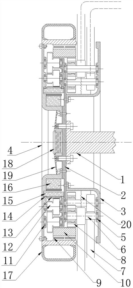
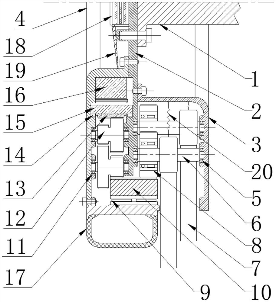
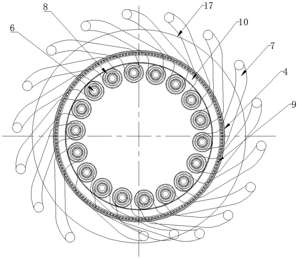
[0028] see Figure 1-5 , the invention provides a gravitational energy generator for motor vehicles, including a wheel hub mounting plate 2 fixedly installed with the vehicle wheel axle half-bridge 1, and an assembly hole 21 for installing the vehicle wheel axle half-bridge 1 is opened in the middle of the wheel hub mounting plate 2, The hub mounting plate 2 can be fixedly installed on the vehicle axle half-axle 1 through bolts;

[0029] The inner side of the hub mounting plate 2 is fix...


PUM


Abstract

The invention discloses a gravity energy generator for a motor vehicle in the technical field of gravity energy, which utilizes the weight of a transport vehicle and adopts a design mode of an automobile hub. A kinetic energy conversion mechanism, a gear speed-up transmission mechanism, a generator mechanism and a power output interface are installed in a hub of the vehicle in a centralized mode,and the vehicle is made to move under the condition that an auxiliary power source provides initial power, due to rotation of the wheels, a plurality of pressure crank arms arranged on the periphery of the hub do lever motion under the action of object gravity and counter-acting force of the ground, the angles of the crank arms are sequentially changed, the weight of a vehicle perpendicular to theground is converted into torque, and the rotating torque is transmitted to a generator through speed increase of a gear transmission device to serve as a generator energy supply source, and the generator generates voltage output, so that the generation of gravity energy is realized; the generator is easy to manufacture, convenient to install, simple in energy expansion and suitable for road traffic vehicles and rail traffic locomotives.

Description

technical field [0001] The invention relates to the technical field of gravity energy, in particular to a gravity energy generator for motor vehicles. Background technique [0002] In today's society with highly developed science and technology, limited energy is decreasing day by day, which will bring immeasurable crisis to future development. Therefore, there have been many research topics and achievements in energy utilization, such as hydrogen energy, air energy, solar energy, and wind energy. , they all have indirect loss of energy and environmental pollution in disguise. Transportation vehicles are an indispensable means of transportation for modern humans. With the rapid development of the world economy and the automobile industry, the number of automobiles and the demand for automobiles have risen sharply, and the accompanying energy and environmental issues have attracted more and more attention. Energy and environmental issues are two major problems facing the wor...

Claims


Application Information

Patent Timeline
IPC IPC(8): H02K7/18H02J7/14
CPCH02J7/1415H02K7/1846Y02T10/92
Inventor 林敬英
Owner 林敬英
Learn More