A welding connection structure between a capacitor and a busbar

A welding connection and capacitor technology, applied in welding/welding connection, components of fixed capacitors, capacitors, etc., can solve the problems of low welding tension, functional failure, and material thickness difference, and achieve reliability requirements and reliability. improved effect

Active Publication Date: 2022-02-18
皇裕精密技术(苏州)有限公司
View PDF4 Cites 1 Cited by
  • Summary
  • Abstract
  • Description
  • Claims
  • Application Information

AI Technical Summary

Problems solved by technology

For products with a busbar thickness of 3mm, due to the large difference in thickness between the two materials, and the thermal conductivity of C1100 is very good, it is difficult to weld the capacitor pins on the busbar with this resistance welding method
Or the capacitor pins have been broken during welding, but the welding tension after welding is still relatively low, and the product will be directly disconnected during vibration test or mechanical shock, resulting in functional failure
In addition, the welding process is more complicated, and it is necessary to fix the busbar and capacitor pins manually or with fixtures.
Finally, it is more difficult to solder nickel-plated products. Generally, bare copper or direct tin plating is used, but it is not suitable for products with high salt spray test requirements.

Method used


Image

  • A welding connection structure between a capacitor and a busbar
  • A welding connection structure between a capacitor and a busbar
  • A welding connection structure between a capacitor and a busbar

Examples


Embodiment Construction

[0016] The present invention will be further described below in conjunction with the accompanying drawings. The following examples are only used to illustrate the technical solution of the present invention more clearly, but not to limit the protection scope of the present invention.

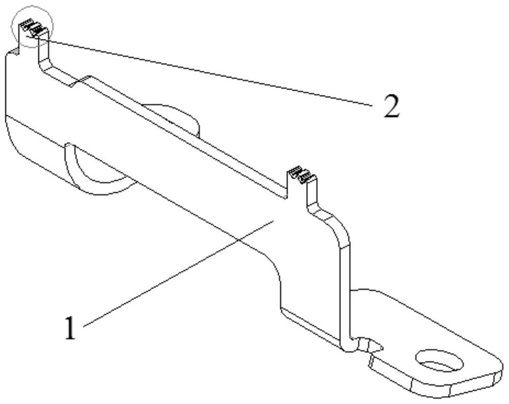
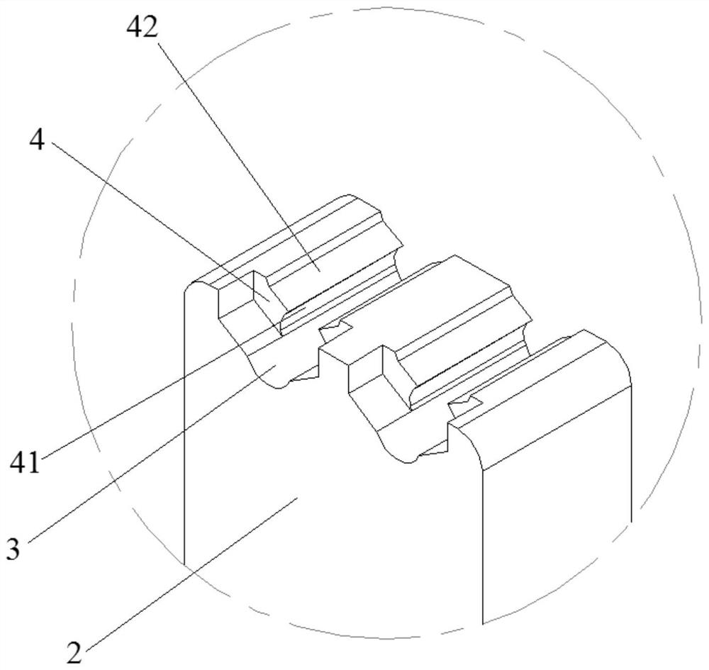
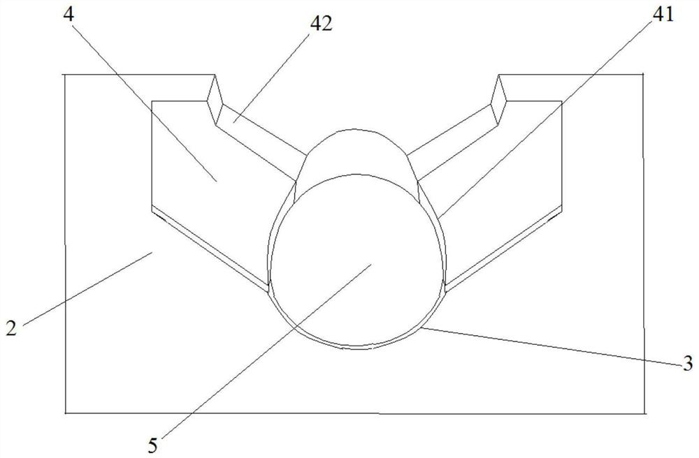
[0017] Such as figure 1 As shown, the present invention provides a welding connection structure between a capacitor and a busbar, including a busbar 1, two capacitor connecting parts 2 are arranged on the busbar 1, two arc-shaped grooves 3 are opened on the capacitor connecting part 2, and the capacitor On the connecting part 2 and on both sides of the arc-shaped groove 3, two clamping parts 4 are integrally connected, and the inside of the clamping part 4 is provided with a clamping curved surface 41, and the two clamping curved surfaces 41 are used to cooperate with the arc-shaped groove 3 On the fixed capacitor pin 5 , the clamping portion 4 is provided with a slotted portion 42 , the rear en...


PUM

PropertyMeasurementUnit
thicknessaaaaaaaaaa
diameteraaaaaaaaaa

Abstract

The invention discloses a welding connection structure between a capacitor and a bus bar, which comprises a bus bar (1), two capacitor connecting parts (2) are arranged on the bus bar (1), and two capacitor connecting parts (2) are arranged on the capacitor connecting part (2). In the arc-shaped groove (3), two clamping parts (4) integrally connected are arranged on the capacitor connecting part (2) and located on both sides of the arc-shaped groove (3), and the inside of the clamping part (4) is provided with a clamping Curved surface (41), two clamping curved surfaces (41) and arc-shaped grooves (3) are used to fix the capacitor pin (5), the clamping part (4) is provided with a grooved part (42), and the clamping part (4) The rear end is flush with the rear end surface of the capacitor connection part (2), and the front end of the clamping part (4) is located behind the front end surface of the capacitor connection part (2). The welding connection structure between the capacitor and the busbar provided by the present invention is a self-clamping structure, which can adapt to different thicknesses of the busbar and different thicknesses of the capacitor pins, and does not require additional clamps to fix the busbar and the capacitor leads. foot.

Description

technical field [0001] The invention relates to a welding connection structure of a capacitor and a bus bar, belonging to the technical field of capacitor pin welding. Background technique [0002] In the prior art, the pins of the busbar and the X&Y capacitors are connected by directly welding the pins on the surface of the busbar. The thickness of the busbar is close to the thickness of the capacitor pins, for example, the capacitor pin is φ0.8mm, and the thickness of the busbar is 1mm. For products with a busbar thickness of 3mm, due to the large difference in thickness between the two materials and the excellent thermal conductivity of C1100, it is difficult to weld the capacitor pins on the busbar with this resistance welding method. Or the capacitor pins have been broken during welding, but the welding tension after welding is still relatively low, and the product is directly disconnected when it is subjected to vibration tests or mechanical shocks, resulting in funct...

Claims


Application Information

Patent Timeline
Patent Type & Authority Patents(China)
IPC IPC(8): H01R4/02H01R4/58H01G2/02H01G4/228B23K33/00H02G5/00
CPCH01R4/02H01R4/58H01G2/02H01G4/228B23K33/00H02G5/00
Inventor 海飞
Owner 皇裕精密技术(苏州)有限公司
Why Eureka
Try Eureka