Tunnel feet-lock anchor rod accurate positioning and construction method

A technology of locking foot bolts and precise positioning, which can be used in the installation of bolts, earthwork drilling, mining equipment, etc. It can solve problems such as tunnel convergence or settlement deformation, affecting the stability of steel frames, and poor connection quality of steel frames, etc., to achieve Good social benefits, improving construction efficiency, and facilitating the installation of steel pipes

Pending Publication Date: 2021-01-26
THE 8TH GRP OF CHINA RAILWAY 1ST ENG CO LTD +1
View PDF5 Cites 1 Cited by
  • Summary
  • Abstract
  • Description
  • Claims
  • Application Information

AI Technical Summary

Problems solved by technology

When the steel frame lock foot anchor pipe is drilled, the external insertion angle is difficult to control, the position is deviated, and the quality of the connection with the steel frame is poor, which affects the stability of the steel frame, easily causes tunnel convergence or settlement deformation, and causes safety and quality accidents such as arch loss

Method used


Image

  • Tunnel feet-lock anchor rod accurate positioning and construction method
  • Tunnel feet-lock anchor rod accurate positioning and construction method
  • Tunnel feet-lock anchor rod accurate positioning and construction method

Examples


Embodiment 2

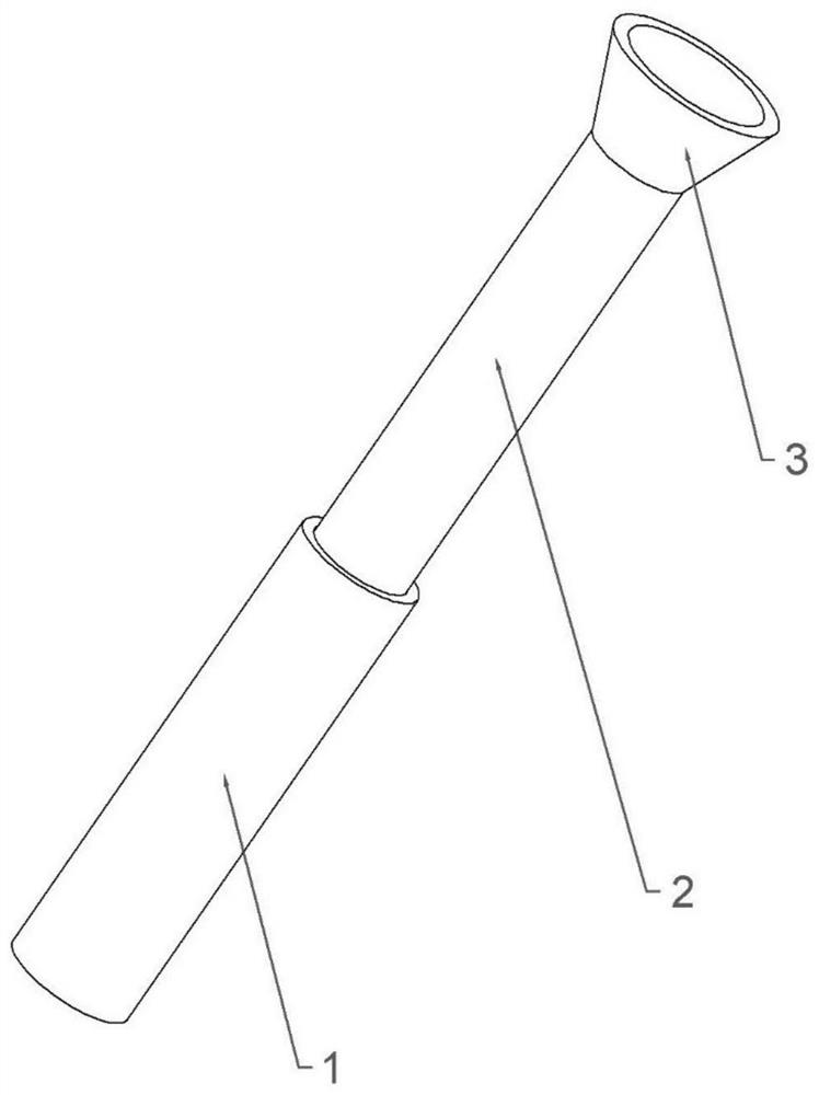
[0046] Such as image 3 , Figure 4 and Figure 5 As shown, the difference between the present embodiment and the first embodiment is that the guide tube 8 in the locking foot anchor tube positioning device in the present embodiment includes an inner tube 2 and an outer tube 1, and the inner tube 2 is located in the outer tube 1 and is in contact with the outer tube 1. The tube 1 is slidably fitted. Specifically, the inner wall of the outer tube 1 is provided with a chute along the axial direction, and the outer side of the inner tube 2 is provided with a convex line along the axial direction. The inner tube 2 is provided with a scale. The end of the inner tube 2 away from the outer tube 1 is provided with a fixed shell 3, which is in the shape of a truncated cone. The inner tube 2 is provided with a positioning ring 5, which is connected to the inner wall of the inner tube 2 through the connecting rod 4, and the number of the positioning rings 5 ​​is multiple and distribut...

Embodiment 3

[0049] Such as Figure 6 As shown, the difference between this embodiment and Embodiment 1 is that the diameter of the positioning ring 5 in this embodiment can be adjusted. Specifically, a plurality of through holes are evenly opened in the circumferential direction of the inner tube 2, and the number of through holes in this embodiment is the same as the number of the connecting rods 4, which are three. The positioning ring 5 is composed of three positioning sub-rings 15 having the same shape, and the three positioning sub-rings 15 can form a circular positioning ring 5 . The three connecting rods 4 pass through the through holes respectively, and the ends of the connecting rods 4 located in the inner tube 2 are connected to the positioning sub-ring 15, and the connection method can be threaded connection, card connection or other connection methods. The outer end of the inner tube 2 is provided with a rotating tube 11, and the rotating tube 11 is slidingly connected with t...


PUM


Abstract

The invention relates to the technical field of building construction, and discloses a tunnel feet-lock anchor rod accurate positioning and construction method. A feet-lock anchor pipe drilling positioning device is used to guide the drilling direction of a drill rod of a drilling machine, and the construction method comprises the following steps that S1, a tunnel face is blasted and excavated; S2, lofting and stationing are conducted, the position of a steel frame is measured and lofted by a measuring group according to the designed mileage and section; S3, the steel frame is installed; the machined and formed small-section steel frame is installed from one side of an arch wall to the other side of the arch wall, the next steel frame is sequentially installed, and reinforcing meshes are synchronously installed; S4, a feet-lock anchor pipe is drilled, the feet-lock anchor pipe positioning device is installed, and the feet-lock anchor pipe is drilled by using the drilling machine; S5, the feet-lock anchor pipe is installed, namely the feet-lock anchor pipe is processed and formed in advance according to design requirements, after hole cleaning, the feet-lock anchor pipe is jacked into the hole by adopting the drilling machine, and a feet-lock anchor pipe connecting rib is welded; and S6, grouting is conducted on the feet-lock anchor pipe. By the adoption of the method, the requirements for drilling and installing of the tunnel feet-lock anchor pipe can be met.

Description

technical field [0001] The invention relates to the technical field of building construction, in particular to a precise positioning and construction method of a tunnel locking foot bolt. Background technique [0002] The lock-foot anchor refers to the bolt that is driven into the vertical rock wall at the arch foot before the next step of construction excavation (that is, the excavation of the lower section) to ensure safety when the tunnel is excavated by the method of arch first and wall behind Anchor to prevent the vault from shrinking and falling off. The characteristics of the drilling and installation of the tunnel lock-foot anchor pipe are that the drilling rig has a large resistance during the drilling process, the drill pipe is easy to swing, and the deviation of the drilling position and the external insertion angle is large; the construction environment is harsh, and personnel are required to assist in fixing the drilling rig during the drilling process. The lab...

Claims


Application Information

Patent Timeline
Patent Type & Authority Applications(China)
IPC IPC(8): E21D20/00E21D20/02
CPCE21D20/003E21D20/021
Inventor 顾刘东张恒唐华许清谢远严光路
Owner THE 8TH GRP OF CHINA RAILWAY 1ST ENG CO LTD
Why Eureka
Try Eureka