
Separation device for centimillimeter particles in flue gas

A particle separation and flue gas technology, which is applied in the manufacture of converters, etc., can solve the problems of easy fouling on the inner wall of the evaporative cooler, no waste, waste of high-temperature energy of the flue gas, etc., to achieve secondary utilization, low energy consumption, The effect of shortening the falling distance

Pending Publication Date: 2021-01-26
BEIJING JINGCHENGKELIN ENVIRONMENTAL PROTECTION TECH +1
View PDF3 Cites 0 Cited by
  • Summary
  • Abstract
  • Description
  • Claims
  • Application Information

AI Technical Summary

Problems solved by technology

[0012] Although the above-mentioned evaporative spray cooling dry dust removal technology can achieve the purpose of rapid cooling and coarse dust removal, it still requires a large amount of circulating water, which is not a real dry dust removal technology, and this technology wastes the high-temperature energy of the flue gas. The evaporative cooler also has the problem of easy fouling on the inner wall during use

Method used


Image

  • Separation device for centimillimeter particles in flue gas
  • Separation device for centimillimeter particles in flue gas
  • Separation device for centimillimeter particles in flue gas

Examples


Embodiment Construction

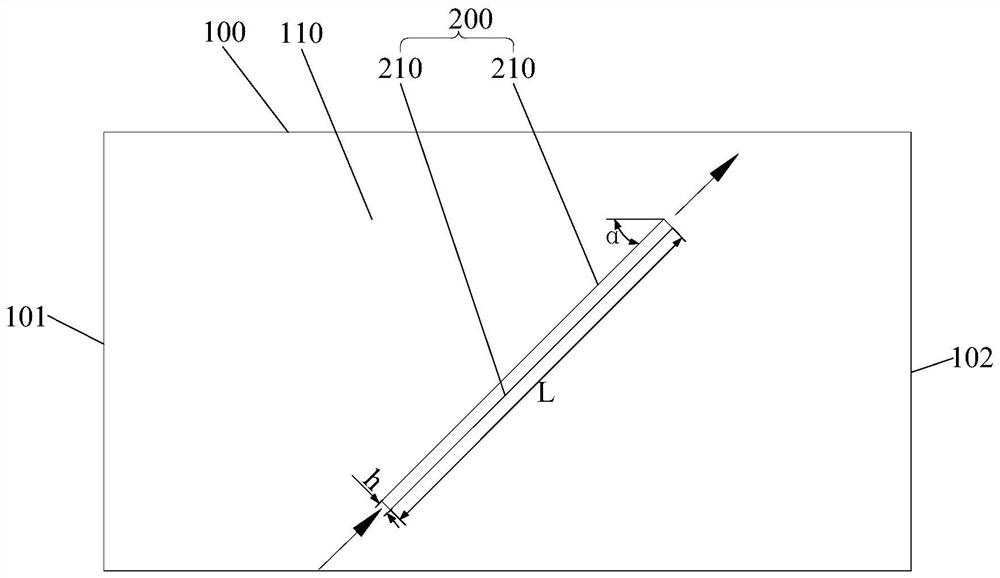
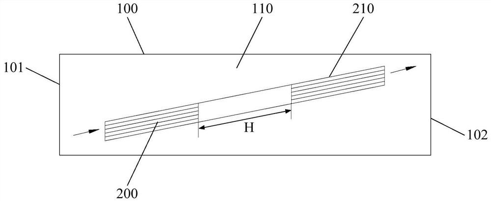
[0034] In order to have a clearer understanding of the technical solutions, objectives and effects of the present invention, the specific implementation manners of the present invention will now be described with reference to the accompanying drawings. Wherein, the use of adjective or adverbial modifiers "inside" and "outside" is only for the convenience of relative reference between groups of terms, and does not describe any specific directional limitation on the modified terms. In the description of the present invention, unless otherwise specified, "plurality" means two or more. exist figure 1 and figure 2 In the figure, the solid line short arrow is the flue gas flow direction, and the meaning of "high temperature" is 650°C to 800°C.

[0035] like figure 1 and figure 2 As shown, the present invention provides a flue gas 10m-level particle separation device, which is arranged in the settling area 110 of the flue gas, and the flue gas 100m-level particle separation dev...


PUM

PropertyMeasurementUnit
lengthaaaaaaaaaa
widthaaaaaaaaaa
particle sizeaaaaaaaaaa

Abstract

The invention provides a separation device for centimillimeter particles in flue gas. The separation device is used for being arranged in a settlement area of a flue duct. The separation device for the centimillimeter particles in the flue gas comprises at least one settlement assembly; each settlement assembly comprises at least two layers of oblique plates which are parallelly arranged at intervals; the oblique plates incline towards the top wall of the flue duct in the flow direction of the flue gas; and the included angle between the oblique plates and the top wall of the flue duct is 5-70degrees. According to the separation device for the centimillimeter particles in the flue gas, the centimillimeter particles in the flue gas can settle down under the action of gravity, so that the aim of separating the particles from the glue gas is achieved.

Description

technical field [0001] The invention relates to the technical field of steelmaking, in particular to a device for separating flue gas nanometer-level particles. Background technique [0002] With the gradual strengthening of the awareness of energy conservation and environmental protection, the research on the recovery of the total waste heat of the converter flue gas and the exploration of the real dry dust removal process have become the focus of many steelmaking plants. However, an important link affecting the development of the converter full-dry waste heat recovery process is how to solve the explosion-proof problem of the converter flue gas in the process. The three factors that cause converter gas to explode are CO concentration of 12.5% ​​to 75%, temperature below 610°C, and ignition with sufficient energy. In order to prevent the explosion, we must consider these three necessary conditions. If one of the necessary conditions is restricted, the explosion will be res...

Claims


Application Information

Patent Timeline
Patent Type & Authority Applications(China)
IPC IPC(8): C21C5/40
CPCC21C5/40
Inventor 杨源满万庆明杨明华穆怀萍周春丽
Owner BEIJING JINGCHENGKELIN ENVIRONMENTAL PROTECTION TECH
Learn More