Foldable and movable refrigeration house

A technology of cold storage and movable panel, applied in the field of cold storage, can solve the problems of loss of cold air and poor thermal insulation effect of cold storage, and achieve the effects of reducing the loss of cold air, good thermal insulation effect and energy saving.

Inactive Publication Date: 2021-01-22
西安思明制冷设备工程有限公司
View PDF2 Cites 1 Cited by
  • Summary
  • Abstract
  • Description
  • Claims
  • Application Information

AI Technical Summary

Problems solved by technology

[0006] The purpose of the present invention is to solve the problem that in the prior art, because it does not have the function of installing a fresh-keeping board on the inner wall of the cold storage, the thermal insulation effect of the cold storage is not good, it is easy to cause the loss of cold air, and it cannot meet the needs of use. , and proposed a kind of collapsible cold storage

Method used


Image

  • Foldable and movable refrigeration house
  • Foldable and movable refrigeration house
  • Foldable and movable refrigeration house

Examples


Embodiment 1

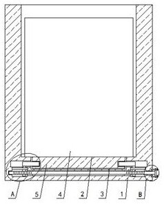
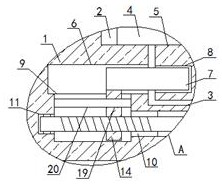
[0024] Example 1 as Figure 1-2 As shown, a foldable and movable cold storage includes a movable plate 1, one side of the movable plate 1 is provided with a placement groove 2 with an opening at the top, and a fixed groove 3 is provided on the inner wall of the bottom of the placement groove 2, and sliding in the placement groove 2 Fresh-keeping plate 4 is installed, and the bottom end of fresh-keeping plate 4 is fixedly installed with fixing plate 5, and the bottom of fixing plate 5 and fixing groove 3 phase snap-fit, all offer sliding groove 6 on the both sides inner walls of fixing groove 3, two sides Sliding plates 7 are slidably installed in each of the sliding slots 6, and both sides of the fixed plate 5 are provided with card slots 8, and the ends of the two sliding plates 7 that are close to each other are respectively engaged with the corresponding card slots 8. The bottom inner wall of the sliding groove 6 is provided with a connecting groove 9, and the same connecti...

Embodiment 3

[0026] Embodiment 3 is such as on the basis of embodiment 1 figure 2 As shown, positioning holes 19 are provided on the two connecting plates 14, positioning rods 20 are slidably installed in the two positioning holes 19, and the two ends of the positioning rods 20 are respectively fixed to the inner wall of one side of the corresponding connecting groove 9. connection, the two positioning rods 20 limit the two connecting plates 14 .

Embodiment 4

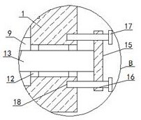
[0027] Embodiment 4 is such as on the basis of embodiment 1 figure 2 As shown, the outer ring of the first bearing is fixedly installed in the rotating groove 11 , and the two-way screw rod 13 is fixedly connected with the inner ring of the first bearing, and the first bearing limits the position of the two-way screw rod 13 .


PUM


Abstract

The invention relates to the technical field of refrigeration houses, and discloses a foldable and movable refrigeration house. The refrigeration house comprises a movable plate; a placing groove withan opening in the top is formed in one side of the movable plate; a fixed groove is formed in the inner wall of the bottom of the placing groove; a fresh-keeping plate is slidably mounted in the placing groove; a fixed plate is fixedly mounted at the bottom end of the fresh-keeping plate; a fixed groove is clamped to the bottom end of the fixed plate; sliding grooves are formed in the inner wallson two sides of the fixed groove correspondingly; sliding plates are slidably mounted in the two sliding grooves correspondingly; clamping grooves are formed in two sides of the fixed plate correspondingly; the ends, close to each other, of the two sliding plates are clamped to the corresponding clamping grooves correspondingly; connecting grooves are formed in the inner walls of the bottoms of the two sliding grooves; and a same connecting hole is formed in the inner walls of the sides, close to each other, of the two connecting grooves. The fresh-keeping plate is additionally arranged on the movable plate, so the heat preservation effect of the refrigeration house is better, the loss of cold air is reduced, energy consumption of the refrigeration house is reduced, and use requirements are met.

Description

technical field [0001] The invention relates to the technical field of cold storage, in particular to a foldable movable cold storage. Background technique [0002] The refrigeration equipment of cold storage basically uses electric energy. With the aggravation of energy crisis and environmental deterioration, the energy consumption of cold storage has become a hot issue. There are two main aspects of energy-saving measures for cold storage, one is to increase the cooling capacity of the refrigeration system. The second is to reduce the loss of cold air in the cold storage. In the second method, it is usually to choose high-quality cold storage building materials, including cold storage body and cold storage door materials. [0003] The application number is: 201720480124.3 discloses a cold storage door, which relates to the technical field of cold storage. The cold storage door includes a door body and an opening and closing device. The opening and closing device is used ...

Claims


Application Information

Patent Timeline
IPC IPC(8): F25D13/00F25D23/06F25D23/00
CPCF25D13/00F25D23/006F25D23/066F25D23/067
Inventor 吕军利
Owner 西安思明制冷设备工程有限公司
Why Eureka
Try Eureka