
Draught fan system, extractor hood with draught fan system and control method of extractor hood

A fan system and control circuit technology, applied in application, pump control, oil fume removal, etc., can solve the problem of not being able to change the working conditions of the whole machine, so as to reduce the impact noise, reduce the impact loss of air flow rate, and improve the whole machine. The effect of efficiency

Active Publication Date: 2021-01-22
NINGBO FOTILE KITCHEN WARE CO LTD
View PDF12 Cites 0 Cited by
  • Summary
  • Abstract
  • Description
  • Claims
  • Application Information

AI Technical Summary

Problems solved by technology

[0009] Common internal diversion devices only have flow control effects at certain operating conditions, and cannot affect the variable operating conditions of the whole machine

Method used


Image

  • Draught fan system, extractor hood with draught fan system and control method of extractor hood
  • Draught fan system, extractor hood with draught fan system and control method of extractor hood
  • Draught fan system, extractor hood with draught fan system and control method of extractor hood

Examples


Embodiment Construction

[0039] Embodiments of the present invention are described in detail below, examples of which are shown in the drawings, wherein the same or similar reference numerals denote the same or similar elements or elements having the same or similar functions.

[0040]In describing the present invention, it should be understood that the terms "center", "longitudinal", "transverse", "length", "width", "thickness", "upper", "lower", "front", " Back", "Left", "Right", "Vertical", "Horizontal", "Top", "Bottom", "Inner", "Outer", "Clockwise", "Counterclockwise", "Axial", The orientation or positional relationship indicated by "radial", "circumferential", etc. is based on the orientation or positional relationship shown in the drawings, and is only for the convenience of describing the present invention and simplifying the description, rather than indicating or implying the referred device or element must have a particular orientation, be constructed, and operate in a particular orientation...


PUM


Abstract

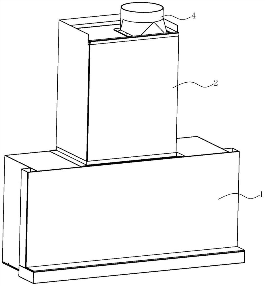
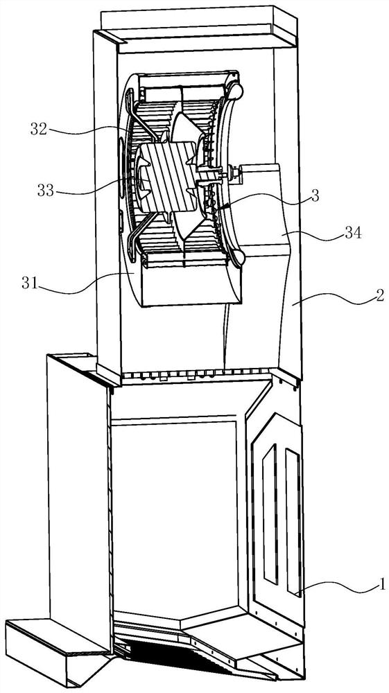
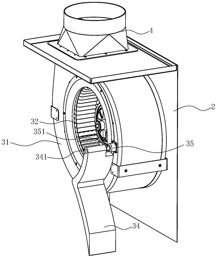
The invention discloses a draught fan system. The draught fan system comprises a volute and an impeller arranged in the volute, and an air inlet is formed in the volute. The draught fan system is characterized in that a flow guiding device used for guiding airflow into the air inlet is arranged at the position, adjacent to the air inlet, outside the volute; when an air outlet of the volute faces upwards, one point passing through the axis of the impeller is taken as a first center, a coordinate system is established by taking the first center as an original point, in the coordinate system, a horizontal line passing through the first center is taken as as an X axis, a vertical line passing through the first center is taken as a Y axis, the side, opposite to the air outlet of the volute, ofthe X axis is taken as the forward direction, and the upward direction of the first center is taken as the forward direction of the Y axis; and the flow guiding device is positioned in a second quadrant of the coordinate system. The invention further discloses an extractor hood with the above draught fan system and a control method of the extractor hood.

Description

technical field [0001] The invention relates to a cooking fume purification device, in particular to a fan system, a range hood using the fan system, and a control method for the range hood. Background technique [0002] Range hoods have become one of the indispensable kitchen appliances in modern families. The range hood uses the principle of fluid dynamics to work, sucks and exhausts the range hood through a centrifugal fan installed inside the range hood, and uses a filter to filter some grease particles. The centrifugal fan includes a volute, an impeller installed in the volute and a motor that drives the impeller to rotate. When the impeller rotates, a negative pressure suction is generated in the center of the fan, and the oil fume under the range hood is sucked into the fan, and after being accelerated by the fan, it is collected by the volute and guided out of the room. [0003] Existing range hoods, as disclosed in Chinese Patent Application No. 201610283257.1, in...

Claims


Application Information

Patent Timeline
Patent Type & Authority Applications(China)
IPC IPC(8): F04D17/16F04D25/06F04D29/42F04D29/44F04D29/66F04D27/00F24C15/20
CPCF04D17/16F04D25/06F04D29/4233F04D29/441F04D29/667F04D29/663F04D27/001F04D27/004F24C15/2021
Inventor 杨伟刚
Owner NINGBO FOTILE KITCHEN WARE CO LTD
Learn More