Eureka AIR delivers breakthrough ideas for toughest innovation challenges, trusted by R&D personnel around the world.

Hydroelectric power generation device capable of generating power in multiple modes

A power generation device and water conservancy technology, applied in the directions of hydroelectric power generation, impact engine, engine components, etc., can solve the problems of a single power generation device, no multiple power generation modes, and little convenience to carry a water conservancy power generation device. Good power generation work and the effect of reducing resistance

Inactive Publication Date: 2021-01-22
福州经济技术开发区易通元智能科技有限公司
View PDF0 Cites 0 Cited by
  • Summary
  • Abstract
  • Description
  • Claims
  • Application Information

AI Technical Summary

Problems solved by technology

[0002] Existing hydroelectric power generation devices are all in the form of large-scale power stations, and there are few portable hydropower generation devices, and the existing power generation devices use water to generate electricity in a relatively simple form, basically using water flow to impact turbines to generate electricity. Moreover, the size of the fan blades of the turbine group is fixed and cannot be changed according to changes in the water flow, and the water must be stored and then released for power generation. Even if there is an easy-to-carry power generation device, there is no way to perform multiple power generation modes and Divide the water to realize the function of effectively impacting power generation. The existing hydroelectric power generation device does not have the function of generating electricity in multiple ways and splitting the water to generate electricity. The hydropower generation device described in the present invention can solve the above problems

Method used


Image

  • Hydroelectric power generation device capable of generating power in multiple modes
  • Hydroelectric power generation device capable of generating power in multiple modes
  • Hydroelectric power generation device capable of generating power in multiple modes

Examples


Embodiment Construction

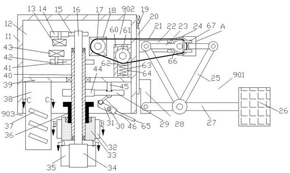
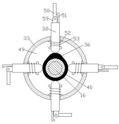
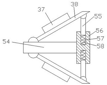
[0017] Combine below Figure 1-5 The present invention is described in detail, wherein, for the convenience of description, the orientations mentioned below are defined as follows: figure 1 The up, down, left, right, front and back directions of the projection relationship itself are the same.

[0018] A hydroelectric power generation device for generating electricity in various ways according to the present invention includes a box body 11, a cavity 12 with an opening downward is arranged in the box body 11, and the inner wall of the cavity 12 is fixed with a 12. A fixed plate 39 separated up and down. The fixed plate 39 is rotatably connected with two rotating sleeves 40 that are symmetrical front and rear and extend up and down. wheel 44, the right side of the runner 44 is meshed with a secondary runner 29, the upper side of the secondary runner 29 is rotatably connected with a rotating shaft 45 fixed to the lower side of the fixed plate 39, and the lower side of the secon...


PUM


Abstract

The invention discloses a hydroelectric power generation device capable of generating power in multiple modes. The hydroelectric power generation device capable of generating power in multiple modes comprises a box body, wherein a cavity with a downward opening is formed in the box body; a fixing plate for vertically separating the cavity is fixed to the inner wall of the cavity and is rotatably connected with two rotating sleeves which are symmetrical in the front-back direction and extend vertically. According to the hydroelectric power generation device capable of generating power in multiple modes provided by the invention, power generation can be conducted through shaking of a water flow, meanwhile, power generation can be conducted through impact of the water flow, the impact area ofthe water flow can be changed through the device according to the different flow speeds of the water flow, and resistance generated by the water flow to power generation can be reduced; and the device has the effects of guiding and shunting the water flow, so that the water flow flows to one side in a centralized manner, and the power generation work is better carried out.

Description

technical field [0001] The invention relates to the field of hydroelectric power generation, in particular to a hydroelectric power generation device for generating electricity in multiple ways. Background technique [0002] Existing hydroelectric power generation devices are all in the form of large-scale power stations, and there are few portable hydropower generation devices, and the existing power generation devices use water to generate electricity in a relatively simple form, basically using water flow to impact turbines to generate electricity. Moreover, the size of the fan blades of the turbine group is fixed and cannot be changed according to changes in the water flow, and the water must be stored and then released for power generation. Even if there is an easy-to-carry power generation device, there is no way to perform multiple power generation modes and Divide the water to realize the function of effectively impacting power generation. The existing hydroelectric ...

Claims


Application Information

Patent Timeline
Patent Type & Authority Applications(China)
IPC IPC(8): F03B13/00F03B11/00F03B1/00
CPCF03B1/00F03B11/002F03B13/00Y02E10/20
Inventor 刘杜奎
Owner 福州经济技术开发区易通元智能科技有限公司
Why Eureka
Eureka Blog
Learn More