
Laser welding longitudinal seam joint guiding, preheating and distressing dynamic correction device for thin-walled cylinder

A thin-walled cylinder and stress-relief technology, which is applied in laser welding equipment, welding equipment, heat treatment furnaces, etc., can solve problems such as cylinder deformation

Active Publication Date: 2021-01-22
CHANGCHUN UNIV OF SCI & TECH
View PDF21 Cites 5 Cited by
  • Summary
  • Abstract
  • Description
  • Claims
  • Application Information

AI Technical Summary

Problems solved by technology

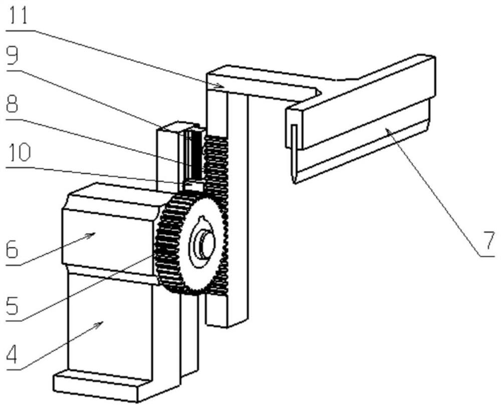
[0007] The purpose of the present disclosure is to provide a laser welding thin-walled cylinder longitudinal seam joint guiding preheating and stress-relief dynamic shape correction device, which can solve the problem of centering and guiding of the laser welding head of the thin-walled cylinder longitudinal seam and preheating before welding Problem; at the same time, this disclosure can carry out online stress relief and dynamic shape correction, use high-temperature shape correction wheels to correct the shape of the cylinder body and eliminate welding residual stress at the same time, and can detect the size of the cylinder body in real time, adjust the position of the shape correction mold synchronously, and solve the problem of cylinder Body deformation after welding

Method used


Image

  • Laser welding longitudinal seam joint guiding, preheating and distressing dynamic correction device for thin-walled cylinder
  • Laser welding longitudinal seam joint guiding, preheating and distressing dynamic correction device for thin-walled cylinder
  • Laser welding longitudinal seam joint guiding, preheating and distressing dynamic correction device for thin-walled cylinder

Examples


Embodiment Construction

[0118] The present disclosure will be further described in detail below with reference to the drawings and embodiments. It can be understood that the specific implementation manners described here are only used to explain relevant content, rather than to limit the present disclosure. It should also be noted that, for ease of description, only parts related to the present disclosure are shown in the drawings. Apparently, the described embodiments are only some of the embodiments of the present disclosure, not all of them. Based on the embodiments in the present disclosure, all other embodiments obtained by persons of ordinary skill in the art without making creative efforts belong to the protection scope of the present disclosure.

[0119]Unless otherwise specified, the illustrated exemplary embodiments / embodiments are to be understood as exemplary features providing various details of some manner in which the technical idea of ​​the present disclosure can be implemented in pr...


PUM


Abstract

The invention discloses a laser welding longitudinal seam joint guiding, preheating and distressing dynamic correction device and method for a thin-walled cylinder, and belongs to the technical fieldof laser welding. The device comprises a supporting mechanism, a longitudinal joint centering and guiding mechanism, double-side self-preheating feeding mechanisms, destressing correction mechanisms and a size detection structure. A blade-shaped guiding body of the device is embedded into the open cylinder, a longitudinal connector is automatically centered and guided, the guiding body is gradually separated from the connector along with opposite movement and enclasping of heating and enclasping wheels on the two sides, centering and guiding of the longitudinal connector are completed, weldingdefects are effectively avoided, the welding quality is improved, and the equipment configuration and investment cost is reduced. Uniform preheating and longitudinal feeding of the cylinder are completed through self-rotation of the heating and enclasping wheels on the two sides; the cylinder is subjected to rolling correction through circumferential high-temperature correction wheels, and meanwhile, the welding residual stress is eliminated; and laser sensors are used for detecting the size of the cylinder in real time, a circumferential shape correcting die is synchronously adjusted, and the problem of welding deformation of the thin-walled cylinder is solved.

Description

technical field [0001] The disclosure belongs to the technical field of laser welding, and in particular relates to a laser welding thin-wall cylinder longitudinal seam joint guiding preheating and stress-relieving dynamic shape correction device. Background technique [0002] Thin-walled cylinders usually refer to cylinders with a wall thickness between 0.5mm and 2.0mm and a pipe diameter in the range of φ100mm to φ600mm, most of which are made of 3-series and 4-series stainless steel. Longitudinal seam welding refers to the welding of the longitudinal seam of the plate after rolling or stamping; this technology is mainly used in the fields of auto parts, home appliances, food and chemical industry. [0003] Laser welding technology is widely used due to its advantages of fast welding speed, narrow weld seam and small heat-affected zone. High-quality welding depends on the relative position accuracy of the laser welding head and the edge of the cylinder to be welded. Due ...

Claims


Application Information

Patent Timeline
IPC IPC(8): B23K26/60B23K26/70B21D3/05B21C51/00C21D9/50
CPCB23K26/70B23K26/702B23K26/60B21D3/05B21C51/00C21D9/50
Inventor 张秋实刘凤德马贝贝方超富张宏李彦清黄根哲
Owner CHANGCHUN UNIV OF SCI & TECH
Learn More