
Conveying mechanism moving along with soil sampling mechanism

A conveying mechanism and displacement technology, which is applied in earth-moving drilling, mining equipment, tunnels, etc., can solve the problems that the conveying device cannot be used in conjunction with the bolt and drill pipe, and the soil conveying efficiency is low.

Active Publication Date: 2021-01-19
江西中恒地下空间科技有限公司
View PDF5 Cites 0 Cited by
  • Summary
  • Abstract
  • Description
  • Claims
  • Application Information

AI Technical Summary

Problems solved by technology

[0004] In the above-mentioned related technologies, the auger drill pipe drills the earthwork, and the soil inside the earthwork moves along the steel sleeve, and is discharged from the excavation funnel to the upper part of the conveyor belt, but the bolt drill pipe needs to move along the excavation place, when the bolt drill pipe Conveyors do not work well with bolted drill pipe when moving, resulting in inefficient soil transfer
[0005] For the related technologies mentioned above, the inventor believes that there is a defect of low soil transport efficiency

Method used


Image

  • Conveying mechanism moving along with soil sampling mechanism
  • Conveying mechanism moving along with soil sampling mechanism
  • Conveying mechanism moving along with soil sampling mechanism

Examples


Embodiment Construction

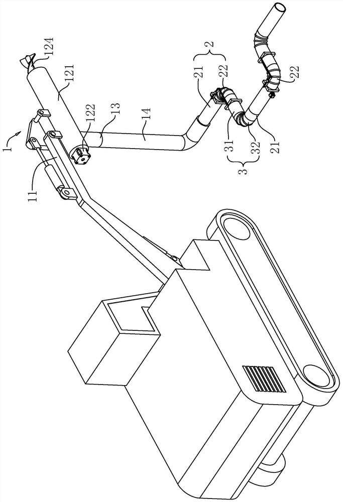
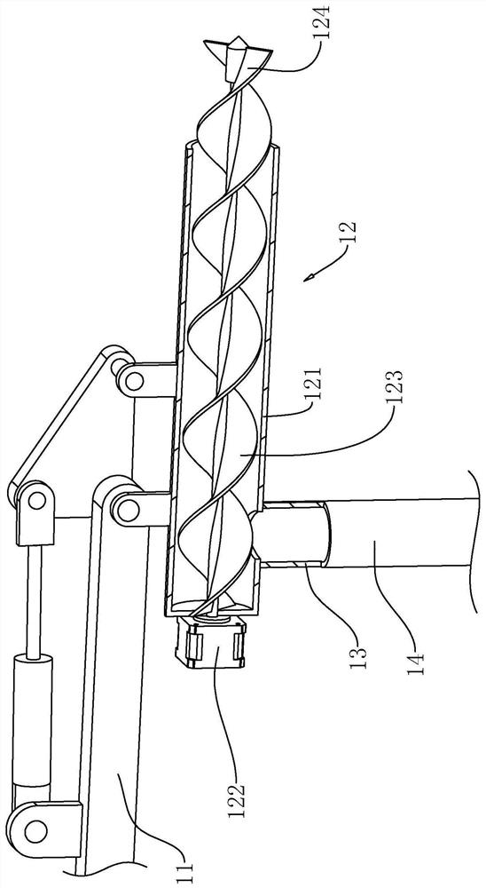
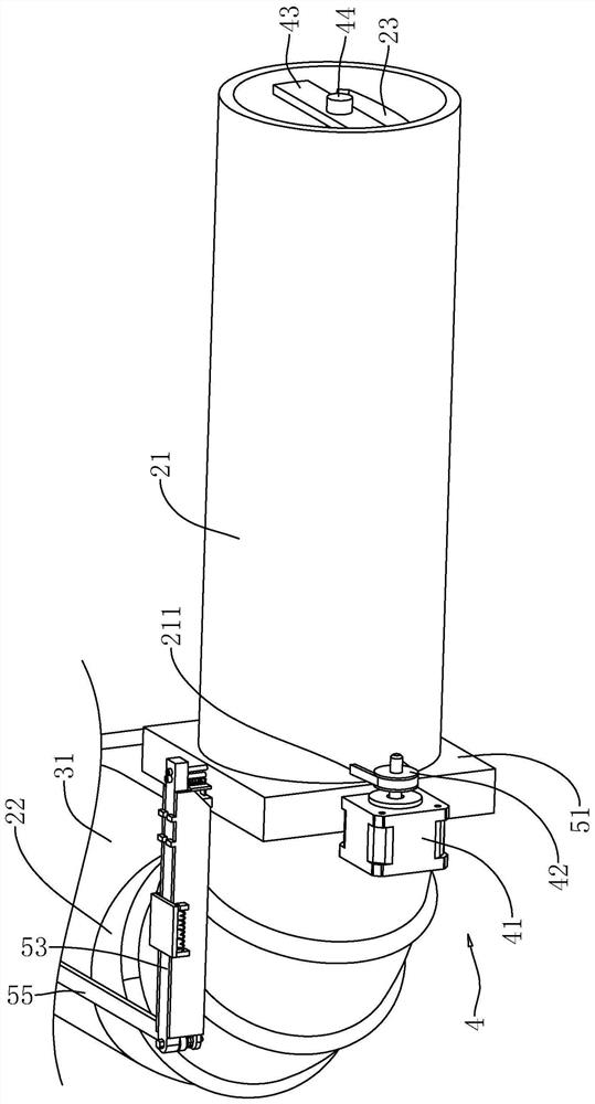
[0037] The following is attached Figure 1-8 The application is described in further detail.

[0038] The embodiment of the present application discloses a conveying mechanism that is displaced with the earth-taking mechanism. refer to Figure 1-2 , the conveying mechanism with the displacement of the earth-taking mechanism is used in conjunction with the earth-boring equipment 1 . The earth drilling equipment 1 comprises a body 11, an earth taker 12 installed on the body 11, and the earth taker 12 includes a steel sleeve 121 installed on the body 11, a power head 122 installed at the tail of the steel sleeve 121, a power head 122 installed on the steel sleeve Inside 121, the auger rod 123 driven by the power head 122 and the excavation bit 124 installed on the end of the auger rod 123 away from the power head 122, the excavation bit 124 stretches into the inside of the earthwork to be excavated, and excavates the earthwork. The bottom of the steel sleeve 121 is communicate...


PUM


Abstract

The invention relates to a conveying mechanism capable of moving along with the soil sampling mechanism. The conveying mechanism comprises a discharging ring installed at a soil outlet of soil drilling equipment, a conveying pipeline is installed at the end, facing away from the soil drilling equipment, of the discharging ring, the conveying pipeline is formed by sequentially connecting a first connecting pipe and a second connecting pipe, and the first connecting pipe comprises a first straight pipe and a first flexible pipe connected to one side of the first straight pipe and used in cooperation with the first straight pipe; the second connecting pipe comprises a second straight pipe and a second flexible pipe connected to one side of the second straight pipe and used in cooperation withthe second straight pipe; and auger pieces are arranged in the first straight pipe and the second straight pipe correspondingly, and driving pieces for driving the augers to rotate are arranged outside the first straight pipe and the second straight pipe. The conveying mechanism has the effect of being high in soil conveying effect.

Description

technical field [0001] The present application relates to the field of earthwork construction, in particular to a conveying mechanism that is displaced with an earth-taking mechanism. Background technique [0002] At present, the reverse construction method is an unconventional construction method, which is generally adopted in special circumstances such as deep foundations, complex geology, and high groundwater levels. Construction of underground diaphragm walls or other supporting structures along the axis of the basement of the building or around it, and at the same time pouring or laying down intermediate support piles and columns at relevant positions inside the building, as a support for bearing the self-weight and construction load of the upper structure before the bottom plate is sealed during the construction period . Then excavate the earthwork to the bottom level of the basement of the first floor, and complete the beam-slab floor structure of this floor. There ...

Claims


Application Information

Patent Timeline
Patent Type & Authority Applications(China)
IPC IPC(8): E21D9/12E21D9/10
CPCE21D9/124E21D9/12E21D9/1006
Inventor 曹开伟罗成名胡志琴谭永强曹端英张鹏
Owner 江西中恒地下空间科技有限公司
Learn More