Plastic pipe packaging machine
A packaging machine and plastic tube technology, applied in the direction of packaging, transportation packaging, transportation and packaging, etc., can solve the problems of cumbersome operation process, low work efficiency, and manpower consumption, and achieve the effects of simple operation, improved work efficiency, and labor saving
- Summary
- Abstract
- Description
- Claims
- Application Information
AI Technical Summary
Problems solved by technology
Method used
Image
Examples
Embodiment 1
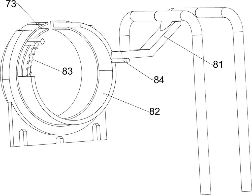
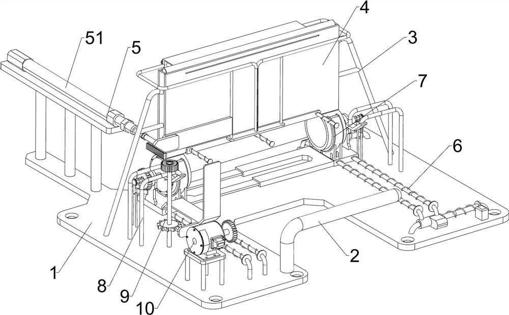
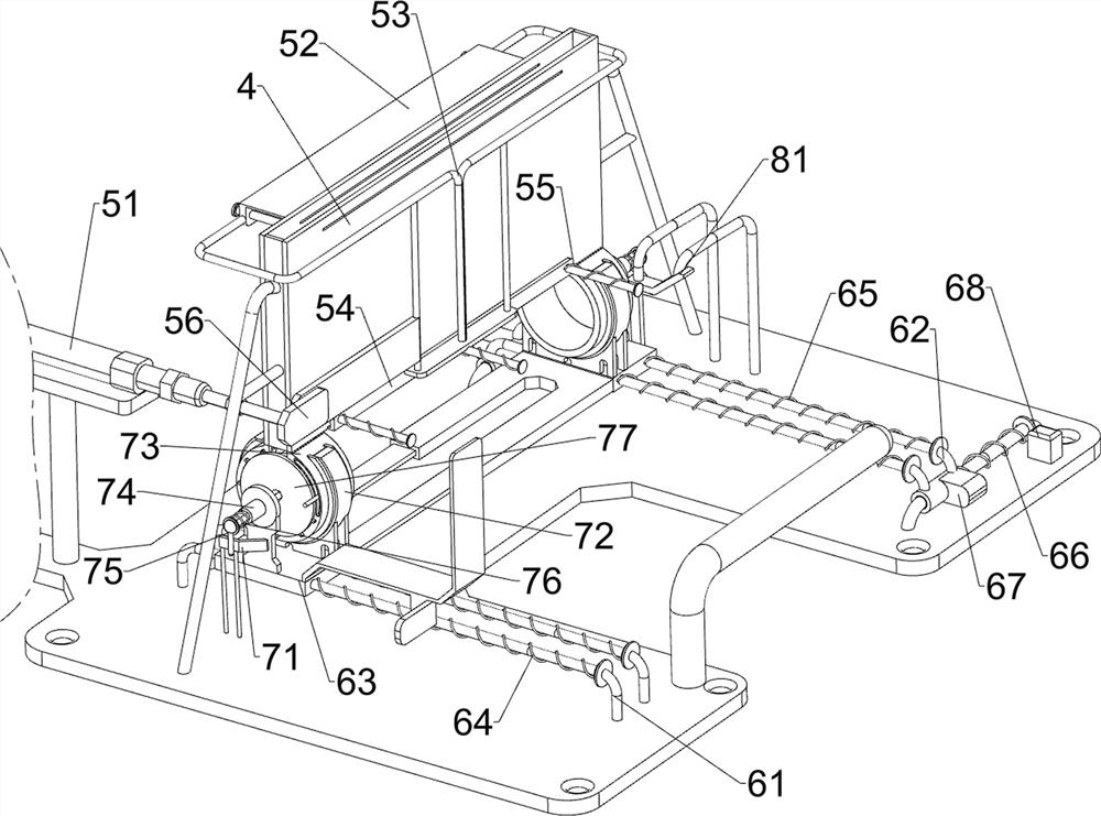
[0026] A plastic tube packaging machine such as Figure 1-3 As shown, it includes an installation base 1, an insertion rod 2, a first connecting frame 3 and a placement frame 4. The front side of the top of the installation base 1 is rotatably connected with the insertion rod 2, and the left and right sides of the rear side of the top of the installation base 1 are Both are connected with a first connecting frame 3, and a placing frame 4 is connected between the first connecting frames 3 on both sides, and also includes a blanking assembly 5, a sliding assembly 6, a receiving assembly 7 and a covering assembly 8, and the installation base 1 A blanking assembly 5 is provided between the placement frame 4, a sliding assembly 6 is provided on the installation base 1, and the sliding assembly 6 is connected to the blanking assembly 5 by transmission. The sliding assembly 6 is provided with a receiving assembly 7, and the receiving assembly 7 A cover assembly 8 is provided between ...
Embodiment 2
[0033] On the basis of Example 1, such as Figure 4 As shown, it also includes a shaking assembly 9, the shaking assembly 9 includes a driving rack 91, a rotating shaft 92, a one-way gear 93, a ratchet gear 94 and a contact rod 95, the connecting plate 56 is connected with a driving rack 91, and the mounting base 1. The rotating shaft 92 is connected on the left side of the top, and the top of the rotating shaft 92 is connected with a one-way gear 93. The driving rack 91 will mesh with the one-way gear 93. The rotating shaft 92 is connected with a ratchet gear 94, and the left sliding frame 63 is connected with a The contact rod 95 and the ratchet gear 94 cooperate with the contact rod 95 .
[0034] When the connecting plate 56 moves forward, it drives the drive rack 91 to move forward. When the drive rack 91 moves forward to mesh with the one-way gear 93, the drive rack 91 continues to move forward and pokes the one-way gear 93 to rotate. The one-way gear 93 rotates to drive...
Embodiment 3
[0036] On the basis of Example 2, such as Figure 4 As shown, a rotating assembly 10 is also included. The rotating assembly 10 includes a servo motor 101, a first transmission gear 102 and a second transmission gear 103. The left front side of the installation base 1 is equipped with a servo motor 101. On the output shaft of the servo motor The first transmission gear 102 is connected, and the second transmission gear 103 is connected to the inner diamond-shaped sleeve 74 on the left side, and the second transmission gear 103 will mesh with the first transmission gear 102 .
[0037] The inner rhombic sleeve 74 drives the second transmission gear 103 to move when moving, and when the second transmission gear 103 moves to mesh with the first transmission gear 102, one side of the packaging film can be pasted on the plastic pipe manually, and after pasting, , the user can start the servo motor 101 to drive the second transmission gear 103 to rotate through the first transmission...
PUM
 Abstract
Description
Claims
Application Information
 - R&D Engineer
- R&D Manager
- IP Professional
- Industry Leading Data Capabilities
- Powerful AI technology
- Patent DNA Extraction
Browse by: Latest US Patents, China's latest patents, Technical Efficacy Thesaurus, Application Domain, Technology Topic, Popular Technical Reports.
© 2024 PatSnap. All rights reserved.Legal|Privacy policy|Modern Slavery Act Transparency Statement|Sitemap|About US| Contact US: help@patsnap.com


