
Paper box forming machine

A technology of forming machine and carton, which is applied in papermaking, paper/cardboard containers, container manufacturing machinery, etc., and can solve the problems of cardboard position deviation, abrasion and scratching of the inner wall of the carton, and deformation of the carton.

Inactive Publication Date: 2021-01-15
GUANGZHOU LIANJIANG SOFTWARE DEV LLC
View PDF0 Cites 0 Cited by
  • Summary
  • Abstract
  • Description
  • Claims
  • Application Information

AI Technical Summary

Problems solved by technology

[0003] At present, there is an existing carton forming machine. When conveying the cut cardboard, because the bottom of the cardboard is smooth, the cardboard slides on the conveyor belt, causing the position of the cardboard to shift, resulting in the folding of the formed cardboard after the pressing plate is pressed down. The carton is deformed, and the pressure plate rubs against the inner wall of the carton when it is lifted after pressing down, causing the inner wall of the carton to be worn and scratched

Method used


Image

  • Paper box forming machine
  • Paper box forming machine
  • Paper box forming machine

Examples


Embodiment 1

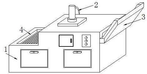
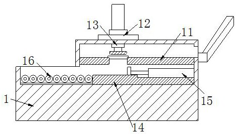
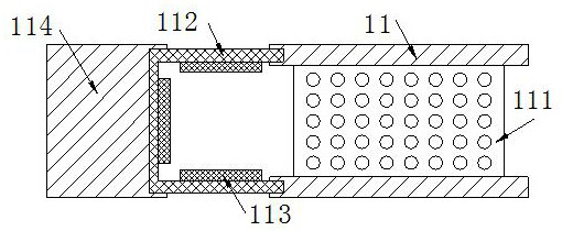
[0029] The present invention provides a carton forming machine, the structure of which includes a forming box 1, an air pipe 2, a feeding plate 3, and a discharge port 4, which are installed on the top of the forming box 1, and the bottom of the feeding plate 3 is connected by welding On the right wall of the forming box 1, the discharge port 4 is embedded on the upper surface of the left side of the forming box 1, and the forming box 1 includes a cardboard conveyor 11, a fixed table 12, an extruder 13, a bottom plate 14, and a push rod 15 , guide roller 16, the right end of the cardboard conveyor 11 is located on the same level as the bottom of the feeding plate 3, and the cardboard conveyor 11 is connected to the inner wall of the forming box 1 by welding, and the bottom of the fixed table 12 is embedded on the upper surface of the forming box 1 , the extruder 13 runs through the fixed table 12 and the upper wall of the forming box 1 and is located above the conveyor 11, the ...

Embodiment 2

[0035]The present invention provides a carton forming machine, the structure of which includes a forming box 1, an air pipe 2, a feeding plate 3, and a discharge port 4, which are installed on the top of the forming box 1, and the bottom of the feeding plate 3 is connected by welding On the right wall of the forming box 1, the discharge port 4 is embedded on the upper surface of the left side of the forming box 1, and the forming box 1 includes a cardboard conveyor 11, a fixed table 12, an extruder 13, a bottom plate 14, and a push rod 15 , guide roller 16, the right end of the cardboard conveyor 11 is located on the same level as the bottom of the feeding plate 3, and the cardboard conveyor 11 is connected to the inner wall of the forming box 1 by welding, and the bottom of the fixed table 12 is embedded on the upper surface of the forming box 1 , the extruder 13 runs through the fixed table 12 and the upper wall of the forming box 1 and is located above the conveyor 11, the b...


PUM


Abstract

The invention discloses a paper box forming machine. The paper box forming machine structurally comprises a forming box, an air conveying pipe, a feeding plate and a discharging port, wherein the airconveying pipe is installed at the top of the forming box, the bottom of the feeding plate is connected to the right wall of the forming box in a welded manner, and the discharging port is embedded inthe upper surface of the left side of the forming box. The paper box forming machine has the advantages that paperboards in the feeding plate fall onto a paperboard conveyer one by one, rotating shafts drive a conveying belt to rotate, then the conveying belt conveys the paperboards, at the moment, anti-slip blocks and anti-slip strips make contact with the bottoms of the paperboards, and thus the situation that the paperboards slip and deviate in the conveying process and paper box forming is affected is avoided; and air pressure in an air pressure cavity is increased when an extruder presses the paperboards, a push plate is pushed to drive a lifting rod to move downwards, pressing plates press the paperboards downwards, air in the air pressure cavity is released after a paper box is formed, then the lifting rod and the push plate rise up, the pressing plates retract inwards under the pull force of tension springs, and thus the situation that the pressing plates abrade or scratch thethe inner wall of the paper box is avoided.

Description

technical field [0001] The invention relates to the field of carton transmission, in particular to a carton forming machine. Background technique [0002] In the packaging industry, the carton forming machine is an indispensable equipment for making cartons. It transports the cut cardboard to the forming tank through the conveyor belt, and presses the press plate to fold the cardboard into a carton shape. And drop down on another conveyor belt for conveying and packaging. [0003] At present, there is an existing carton forming machine. When conveying the cut cardboard, because the bottom of the cardboard is smooth, the cardboard slides on the conveyor belt, causing the position of the cardboard to shift, resulting in the folding of the formed cardboard after the pressing plate is pressed down. The carton is deformed, and the pressure plate rubs against the inner wall of the carton when it is lifted after being pressed down, causing the inner wall of the carton to be worn a...

Claims


Application Information

Patent Timeline
Patent Type & Authority Applications(China)
IPC IPC(8): B31B50/02B31B50/04
CPCB31B50/022B31B50/042
Inventor 梁秀
Owner GUANGZHOU LIANJIANG SOFTWARE DEV LLC
Learn More