Synchronous vibration back-up roll device with frame

A technology of synchronous vibration and supporting rolls, which is applied in the fields of metal solidification and continuous casting, and can solve problems such as no equipment structure scheme given

Pending Publication Date: 2021-01-15
ZHONG NAT ENG & RES CENT
View PDF2 Cites 0 Cited by
  • Summary
  • Abstract
  • Description
  • Claims
  • Application Information

AI Technical Summary

Problems solved by technology

However, the above-mentioned patents or applications only provide technical ideas, a...

Method used


Image

  • Synchronous vibration back-up roll device with frame
  • Synchronous vibration back-up roll device with frame
  • Synchronous vibration back-up roll device with frame

Examples


Embodiment Construction

[0070] The present invention will be further described below in conjunction with the accompanying drawings and embodiments.

[0071] Vibration support rollers and vibration source bodies are arranged on the inner and outer arc directions of the slab

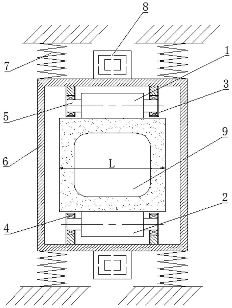
[0072] like figure 1 As shown, a synchronous vibrating support roll device with a frame includes: an inner arc vibrating support roll 1, an outer arc vibrating support roll 2, a first bearing 3, a first bearing seat 4, a support shaft 5, a vibrating frame 6, a first A spring 7, a vibration source body 8.

[0073]When in use, the vibration source body 8 driven by an external force drives the entire vibration frame 6 to vibrate, and the vibration is applied to the slab shell of the casting slab 9 through the vibration support rollers 1 and 2 .

[0074] The device can realize synchronous vibration in the direction of the inner and outer arcs of the casting slab, so that the thick central equiaxed crystals of the slab in the late...


PUM

PropertyMeasurementUnit
Diameteraaaaaaaaaa

Abstract

The invention relates to a synchronous vibration back-up roll device with a frame. The device comprises at least one pair of vibration back-up rolls in contact with a casting blank, a back-up shaft penetrating through the vibration back-up rolls and at least two vibration sources, and further comprises the vibration frame arranged around the casting blank and the vibration back-up rolls. The vibration back-up rolls are symmetrically arranged on the inner side of the vibration frame, and the inner side of the vibration frame vibrates the casting blank through the vibration back-up rolls. The vibration sources are arranged on the outer side or the inner side of the vibration frame, the vibration sources are driven by external force, and vibration is applied to a blank shell of the casting blank through the vibration frame and the vibration back-up rolls. The device can realize synchronous vibration of inner and outer arcs and/or the width direction of the casting blank, so that a large number of dendrites at the solidification front edge of a primary green body shell are broken off to become a source of central solidification isometric crystals, thick central isometric crystals of the casting blank in the later solidification period can be uniformly broken, the solidification structure is refined, and the quality of the casting blank is effectively improved.

Description

technical field [0001] The invention relates to the field of metal solidification and continuous casting, in particular to a synchronous vibrating support roll device with a frame. Background technique [0002] Electromagnetic stirring technology such as mold electromagnetic stirring is to place an electromagnetic induction coil or agitator outside the continuous casting mold. When the electromagnetic induction coil or agitator is fed with an alternating current of a certain frequency, an electromagnetic field will be generated, and the magnetic field will penetrate The crystallizer copper plate and the metal solidify the shell and generate an induced current in the liquid metal. The liquid metal is equivalent to a carrier fluid. The carrier fluid is affected by the magnetic field and generates electromagnetic force in the carrier fluid, thereby causing the liquid metal to produce forced convection. The flowing liquid metal will scour the front of the solidified shell and br...

Claims


Application Information

Patent Timeline
IPC IPC(8): B22D11/114B22D11/12B22D11/128
CPCB22D11/114B22D11/12B22D11/1287
Inventor 赵文博邓建军张慧许斌王明林韩健朱坦华贾广如王强
Owner ZHONG NAT ENG & RES CENT
Why Eureka
Try Eureka