Automatic condensation treatment auxiliary device for water-cooled electronic radiator

A technology of automatic processing and auxiliary devices, applied in the installation of electrical equipment casings/cabinets/drawers, electrical components, and support structures, etc., can solve problems such as labor consumption, equipment insulation degradation, short-circuit faults, and harsh working environment requirements. Effectiveness of workload, prevention of increase in air humidity, and prevention of short-circuit failure

Inactive Publication Date: 2021-01-12
武义县达香电子有限公司
View PDF0 Cites 2 Cited by
  • Summary
  • Abstract
  • Description
  • Claims
  • Application Information

AI Technical Summary

Problems solved by technology

[0002] When the weather is relatively hot and humid, the current water-cooled electronic radiator is prone to condensation. If you do not pay attention, it is very easy to cause the insulation of the equipment to drop and cause a short circuit fault. In order to prevent condensation, relevant personnel need to pay attention to the ambient temperature and cooling. The temperature difference of the water is large, and the requirements for the working environment are more stringent. At the same time, the relevant personnel should stop the water immediately after closing the switch knife, and close the switch immediately after turning on the water when starting up. Closely connected, the operation is relatively cumbersome. On the other hand, if the condensation is manually processed, it will consume manpower

Method used


Image

  • Automatic condensation treatment auxiliary device for water-cooled electronic radiator
  • Automatic condensation treatment auxiliary device for water-cooled electronic radiator
  • Automatic condensation treatment auxiliary device for water-cooled electronic radiator

Examples


Embodiment Construction

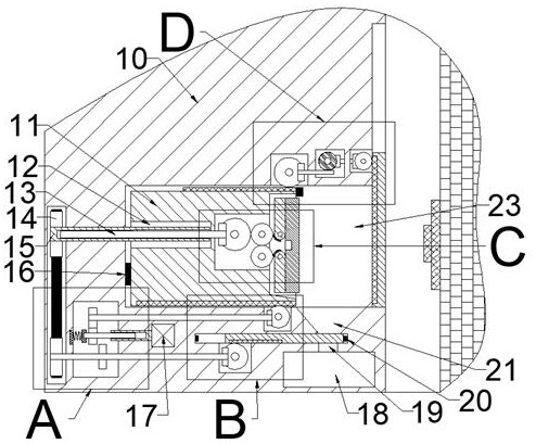
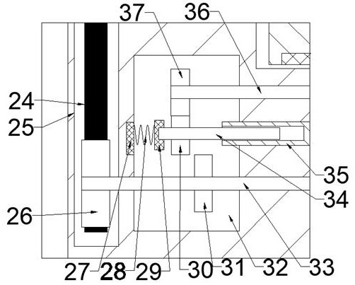
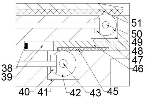
[0018] Combine below Figure 1-5 The present invention is described in detail, wherein, for the convenience of description, the orientations mentioned below are defined as follows: figure 1 The up, down, left, right, front and back directions of the projection relationship itself are the same.

[0019]A water-cooled electronic radiator automatic condensation treatment auxiliary device described in conjunction with accompanying drawings 1-5 includes an equipment box 10, a slide chamber 23 is provided inside the equipment box 10, and the front and rear ends of the slide chamber 23 are A sliding seat 11 is slidably connected between the walls, and a linkage rack 78 is fixedly connected to the upper surface of the sliding seat 11. A long shaft sleeve cavity 12 with an opening to the left is provided inside the sliding seat 11. The lower end of the sliding seat 11 A sliding gear 51 is fixedly connected to the end face, and an extrusion belt chamber 25 extending downward is provide...


PUM


Abstract

The invention relates to the related field of electronic radiators, and discloses an automatic condensation treatment auxiliary device for a water-cooled electronic radiator. The device comprises an equipment box body, a sliding seat cavity is formed in the equipment box body, a sliding seat is connected between the front end wall and the rear end wall of the sliding seat cavity in a sliding fit manner, and the upper end surface of the sliding seat is fixedly connected with a linkage rack; a long shaft sleeve cavity with a leftward opening is formed in the sliding seat. A gear for sliding is fixedly connected into the lower end face of the sliding base, an extrusion belt cavity extending downwards is formed in the left side of the sliding base cavity, and a long shaft sleeve extending rightwards into the long shaft sleeve cavity and extending leftwards into the extrusion belt cavity is connected into the right end wall of the extrusion belt cavity in a running fit mode. The adsorptioncotton can be in full contact with the water-cooled electronic radiator. Condensation is automatically adsorbed, so that a short-circuit fault caused by insulation reduction of equipment due to condensation is prevented as much as possible, half gear rings of upper and lower side pressing plates drive the upper and lower side pressing plates to extrude adsorption cotton, discharging work of the condensation is achieved, and the workload of manual treatment is reduced.

Description

technical field [0001] The invention relates to the related field of electronic radiators, in particular to an auxiliary device for automatic condensation treatment of water-cooled electronic radiators. Background technique [0002] When the weather is relatively hot and humid, the current water-cooled electronic radiator is prone to condensation. If you do not pay attention, it is very easy to cause the insulation of the equipment to drop and cause a short circuit fault. In order to prevent condensation, relevant personnel need to pay attention to the ambient temperature and cooling. The temperature difference of the water is large, and the requirements for the working environment are more stringent. At the same time, the relevant personnel should stop the water immediately after closing the switch knife, and close the switch immediately after turning on the water when starting up. Closely connected, the operation is relatively cumbersome. On the other hand, if the condensa...

Claims


Application Information

Patent Timeline
Patent Type & Authority Applications(China)
IPC IPC(8): H05K5/02H05K5/06H05K7/14F26B5/16
CPCF26B5/16H05K5/0217H05K5/06H05K7/14
Inventor 李梦希
Owner 武义县达香电子有限公司
Why Eureka
Try Eureka