
Gas protection device and method for continuous laser welding

A gas protection device and laser welding technology, applied in laser welding equipment, welding equipment, metal processing equipment, etc., can solve problems affecting welding quality and welding penetration, laser beam shielding effect, pollution protection lens, etc., to reduce welding Slit pores, increase the effective utilization rate, and reduce the effect of shielding effect

Inactive Publication Date: 2021-01-12
WUHAN FARLEYLASERLAB CUTTING SYST ENG
View PDF6 Cites 2 Cited by
  • Summary
  • Abstract
  • Description
  • Claims
  • Application Information

AI Technical Summary

Problems solved by technology

[0002] Laser welding is to focus the laser beam in a small area through the optical system, and form a heat source area with high energy concentration in the welded part in a very short time, so that the welded part can be melted and recrystallized to form a firm solder joint And the weld seam, in the process of laser welding, the surface of the welded workpiece absorbs a large amount of heat and quickly melts and further vaporizes, forming a plume above the welded workpiece, which absorbs and scatters the laser light on the incident path of the laser beam. This will affect the welding quality and welding penetration. After absorbing energy, the plume will easily generate plasma. After the plasma is formed, it will absorb and refract the laser, which will have a shielding effect on the laser beam, and then affect the welding penetration again. At the same time, if laser welding Without effective protective measures and methods, the welding gas or shielding gas can easily enter the molten pool in the form of bubbles and remain in the weld seam, forming pores. In addition, spatter is easily generated during laser welding, and the spatter will pollute the laser. The protective lens of the welding head, which affects the welding quality

Method used


Image

  • Gas protection device and method for continuous laser welding
  • Gas protection device and method for continuous laser welding
  • Gas protection device and method for continuous laser welding

Examples


Embodiment Construction

[0029] The following will clearly and completely describe the technical solutions in the embodiments of the present invention with reference to the accompanying drawings in the embodiments of the present invention. Obviously, the described embodiments are only some, not all, embodiments of the present invention. Based on the embodiments of the present invention, all other embodiments obtained by persons of ordinary skill in the art without making creative efforts belong to the protection scope of the present invention.

[0030] In describing the present invention, it is to be understood that the terms "center", "upper", "lower", "front", "rear", "left", "right", "vertical", "horizontal", The orientations or positional relationships indicated by "top", "bottom", "inner", "outer", etc. are based on the orientations or positional relationships shown in the drawings, and are only for the convenience of describing the present invention and simplifying the description, rather than in...


PUM


Abstract

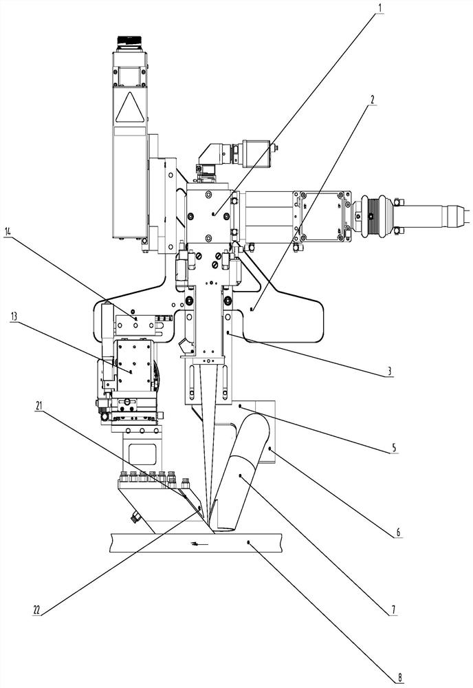
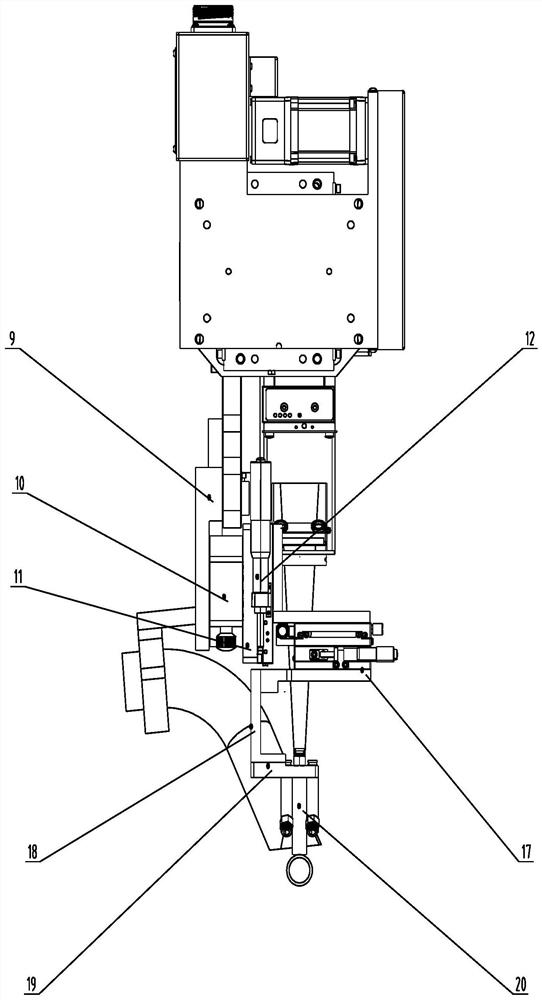
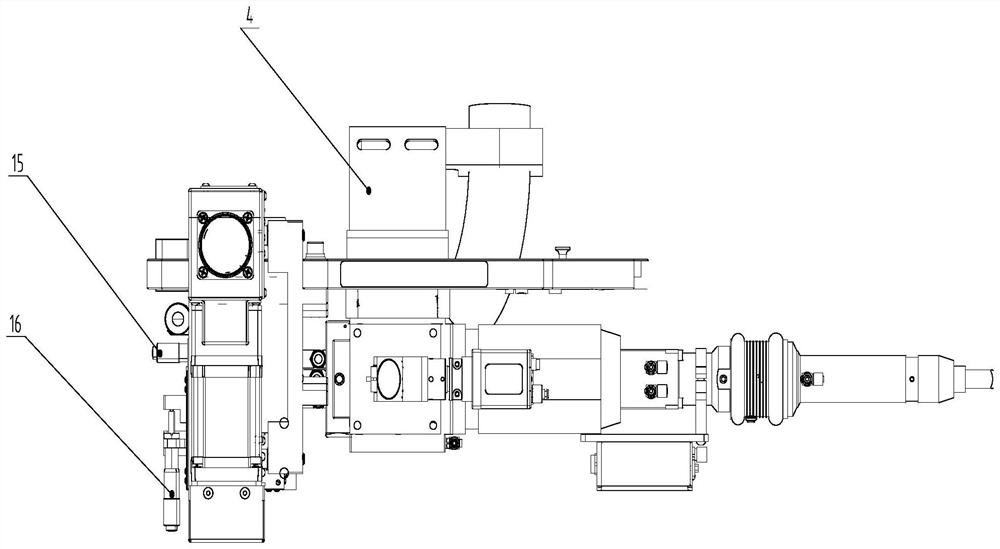
The invention belongs to the technical field of laser welding, and particularly provides a gas protection device and method for continuous laser welding. The method comprises the steps of aligning a gas outlet of an air knife block to a weld joint by adjusting the position and posture of the air knife block; controlling a high-pressure air transverse blowing module at the laser welding position toemit high-pressure air for transversely blowing the weld joint to blow away splashes at the welding position; controlling a mixed shielding gas module at the laser welding position to emit high-pressure mixed gas to protect a weld pool; controlling a weld joint rear high-temperature area shielding gas module to emit inert gas so as to protect the weld joint against oxidation; controlling an air knife cooling module to cool the air knife block; and controlling a suction module to suck the weld joint. Correct air blowing and protection can effectively protect the weld pool so that oxidation canbe reduced or even avoided; splashing generated in the welding process is effectively reduced; the weld pool is promoted to be uniformly spread during solidification, so that the weld joint is uniform and attractive; and the shielding effect of metal steam plume or plasma cloud on laser is effectively reduced.

Description

technical field [0001] The invention belongs to the technical field of laser welding, and in particular relates to a gas protection device and method for continuous laser welding. Background technique [0002] Laser welding is to focus the laser beam in a small area through the optical system, and form a heat source area with high energy concentration in the welded part in a very short time, so that the welded part can be melted and recrystallized to form a firm solder joint And the weld seam, in the process of laser welding, the surface of the welded workpiece absorbs a large amount of heat and quickly melts and further vaporizes, forming a plume above the welded workpiece, which absorbs and scatters the laser light on the incident path of the laser beam. This will affect the welding quality and welding penetration. After absorbing energy, the plume will easily generate plasma. After the plasma is formed, it will absorb and refract the laser, which will have a shielding eff...

Claims


Application Information

Patent Timeline
IPC IPC(8): B23K26/12B23K26/24B23K26/70
CPCB23K26/123B23K26/24B23K26/702B23K26/703
Inventor 王鹏李云兰祁小勇李明叶祖福吴苶
Owner WUHAN FARLEYLASERLAB CUTTING SYST ENG
Learn More