
Real-time identification method for current transformer entering and exiting magnetic saturation state

A technology of current transformers and transformers, which is applied in the direction of instruments, measuring electrical variables, and magnetic performance measurement, etc., can solve the problems of poor real-time performance of wavelet analysis method, large amount of calculation, and derivative method is susceptible to noise interference, etc., and achieves fast detection speed , small amount of calculation, good real-time effect

Active Publication Date: 2022-03-01
STATE GRID HUNAN ELECTRIC POWER +2
View PDF9 Cites 0 Cited by
  • Summary
  • Abstract
  • Description
  • Claims
  • Application Information

AI Technical Summary

Problems solved by technology

Among them, the differential method has low anti-interference ability, and cannot accurately judge the mild saturation of TA; the derivative method is susceptible to noise interference, and the threshold setting is difficult; the harmonic braking method cannot determine the time when TA enters and exits saturation in real time, and is easily affected by harmonics and transient DC components. The impact of the impedance calculation method is limited by the resistance and inductance model and the line voltage signal, and the amount of calculation is large; the wavelet analysis method has poor real-time performance and is susceptible to noise interference; the adaptability of the mathematical morphology method needs to be strengthened, and it is easily affected by harmonics; Hill Unexplained negative frequencies and apparent endpoint effects with Burt-Huang transformation law

Method used


Image

  • Real-time identification method for current transformer entering and exiting magnetic saturation state
  • Real-time identification method for current transformer entering and exiting magnetic saturation state
  • Real-time identification method for current transformer entering and exiting magnetic saturation state

Examples


Embodiment Construction

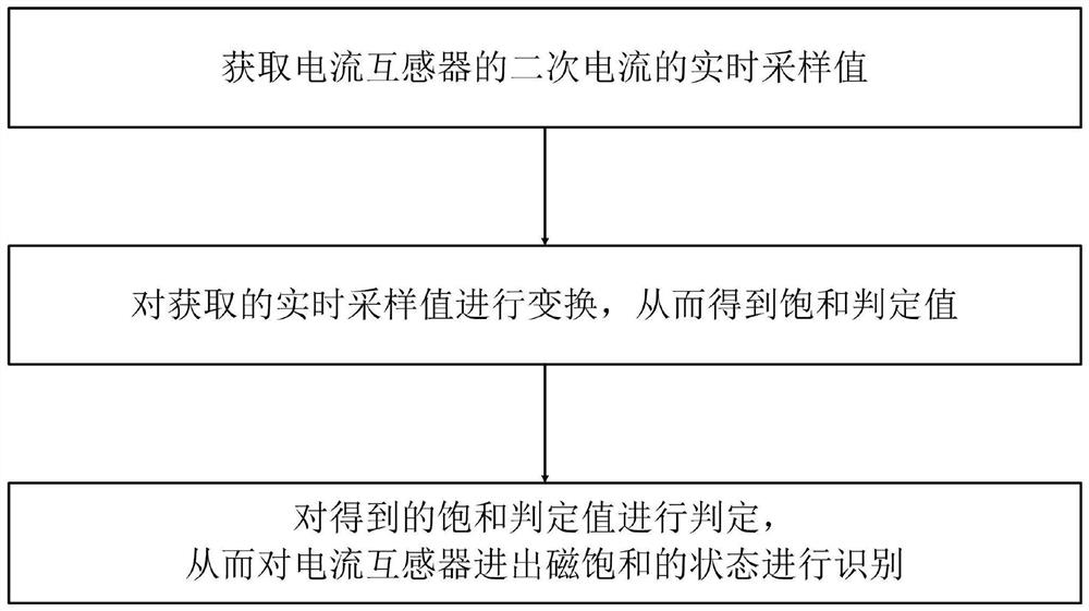
[0040] Such as figure 1 Shown is a schematic flow chart of the method of the present invention: the real-time identification method of the current transformer entering and leaving the magnetic saturation state provided by the present invention includes the following steps:

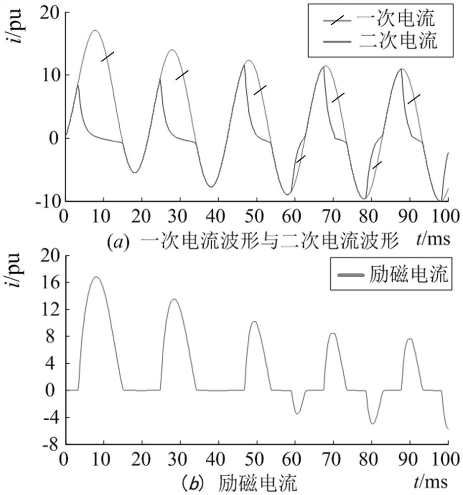
[0041] S1. Obtain the real-time sampling value of the secondary current of the current transformer (the current waveform of the current transformer is as follows figure 2 shown);

[0042] S2. Transform the real-time sampling value obtained in step S1 to obtain the saturation judgment value; specifically, the following steps are used to obtain the saturation judgment value:

[0043] A. Use the following formula to define the intermediate variable G(t):

[0044]

[0045] In the formula, i(t) is the real-time sampling value of the secondary current of the current transformer at time t; Δt is the sampling period; i(t-2Δt), i(t-Δt) and i(t) are three consecutive The real-time sampling value of the second...


PUM


Abstract

The invention discloses a real-time identification method for a current transformer entering and exiting a magnetic saturation state, which comprises acquiring the real-time sampling value of the secondary current of the current transformer and transforming it to obtain a saturation judging value; judging according to the saturation judging value and completing the identification of the current transformer The state of entering and exiting magnetic saturation is identified. The present invention judges TA saturation through linear operation of 5 continuous sampling points, and only needs 4 addition and subtraction and 1 multiplication operation for each judgment, with small amount of computation, fast detection speed, and easy implementation; and during the saturation period, the conversion value The reverse change of D effectively isolates the saturated input signal and the exit signal, and solves the problem that the slightly saturated input and output signals are easy to overlap; finally, the method of the present invention is applicable to different short circuit levels, different DC offset degrees, different residual magnetism, different nature load and noise conditions. Therefore, the method of the invention has high reliability, good real-time performance, fast operation speed and easy implementation.

Description

technical field [0001] The invention specifically relates to a real-time identification method for a current transformer entering and exiting a magnetic saturation state. Background technique [0002] With the development of economy and technology and the improvement of people's living standards, electric energy has become an indispensable secondary energy source in people's production and life, bringing endless convenience to people's production and life. Therefore, the stable and reliable operation of the power system has become one of the most important tasks of the power system. [0003] A current transformer (Current Transformer, TA) is essentially a magnetic component, which is an important part of a power system and is widely used in current sampling occasions. The saturation of the current transformer will distort the secondary current waveform, which may cause malfunction, delayed action or refusal of the relay protection device. Therefore, it is of great signific...

Claims


Application Information

Patent Timeline
Patent Type & Authority Patents(China)
IPC IPC(8): G01R33/12G01R35/02
CPCG01R33/12G01R35/02
Inventor 罗春辉瞿纲举曾兆杰李典谢佳刘珺瑶胡鑫蒋嘉栋
Owner STATE GRID HUNAN ELECTRIC POWER
Learn More