Eureka AIR delivers breakthrough ideas for toughest innovation challenges, trusted by R&D personnel around the world.

A pressure control valve for a closed drainage device capable of controlling negative pressure input

A pressure control valve and negative pressure technology, applied in the direction of valve operation/release device, valve device, valve, etc., can solve the problems of aggravating the disease, the negative pressure cannot be too large, wound infection, etc., to prevent patient discomfort, replacement and other problems. The effect of easy maintenance

Active Publication Date: 2022-07-05
福州骏格科技有限公司
View PDF0 Cites 0 Cited by
  • Summary
  • Abstract
  • Description
  • Claims
  • Application Information

AI Technical Summary

Problems solved by technology

[0004] During the treatment of the existing negative pressure sealing drainage technology, the negative pressure source may be stopped due to unexpected circumstances. At this time, if the input of the irrigation fluid is not turned off in time, the irrigation fluid will accumulate in the confined space, and even lead to the entire negative pressure sealing. The drainage needs to be replaced again, which will lead to further infection of the wound and aggravate the condition; moreover, the negative pressure input by the negative pressure source should not be too large, which will cause discomfort to the patient's wound

Method used


Image

  • A pressure control valve for a closed drainage device capable of controlling negative pressure input
  • A pressure control valve for a closed drainage device capable of controlling negative pressure input

Examples


Embodiment 1

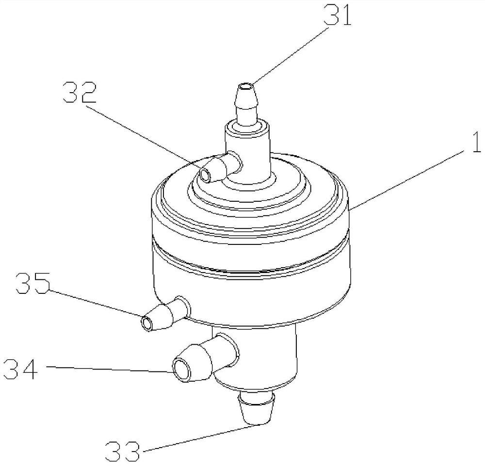
[0022] see figure 1 and figure 2 , a pressure control valve for a closed drainage device that can control negative pressure input, comprising a valve body 1, a cavity is set in the middle of the valve body 1, and a movable piece 2 is movably arranged in the cavity, and the movable piece 2 The cavity is divided up and down into an upper cavity and a lower cavity; the outer wall of the valve body 1 is provided with a water inlet 31 and a water outlet 32 ​​communicating with the upper cavity, and an air inlet 33 and an air outlet communicating with the lower cavity. 34 and monitoring port 35; the upper cavity is provided with a first channel 101 connecting the water inlet 31 and the water outlet 32, the upper end of the movable member 2 is fixedly connected with a water stop rod 21, the water stop rod 21 The upper end of the water stop rod 21 is set in the first channel 101, and the outer side wall of the water stop rod 21 is fixedly sleeved with a sealing ring 22; the lower ca...

Embodiment 2

[0030] The difference between this embodiment and the first embodiment is that the valve body 1 includes an upper valve body 11 and a lower valve body 12 that are detachably connected, and the upper valve body 11 and the lower valve body 12 can be connected by screw connection or snap connection ; The upper valve body 11 is hollow and the lower end is open, the movable member 2 is arranged in the upper valve body 11, and the water inlet 31 and the water outlet 32 ​​are opened on the outer wall of the upper valve body 11. In this embodiment, the water inlet 31 is opened on the top of the upper valve body 11, and the water outlet 32 ​​is opened on the side of the upper valve body 11; the lower valve body 12 is hollow and has an open upper end, and one end of the elastic member 4 is connected to the other side of the upper valve body 11. The movable member 2 is fixedly connected, and the other end is fixedly connected to the inner wall of the lower valve body 12. In this embodimen...

Embodiment 3

[0033]Preferably, in this embodiment, the movable member 2 is set as three parts: an elastic film 23 , a connection fixing member 24 and a film pressing sheet 25 ; the elastic film 23 is horizontally arranged in the cavity, and the connection fixing member 24 The bottom end of the water stop rod 21 is vertically penetrated into the interior of the connecting fixing member 24 and is fixedly connected to the connecting fixing member 24; the top end of the connecting rod is vertical The membrane pressing piece 25 is fixedly sleeved on the lower end of the connecting fixing piece 24, and the top of the membrane pressing piece 25 is connected to the connecting piece 24. The elastic film 23 is fixedly connected.

[0034] The working principle of this embodiment is as follows:

[0035] When the inside of the closed drainage device is in a negative pressure state, the elastic film 23 is attracted to the lower cavity, the middle of the elastic film 23 moves under the action of negativ...


PUM


Abstract

The invention relates to a pressure control valve for a closed drainage device capable of controlling negative pressure input. The outer wall of the valve body is provided with a water inlet, a water outlet, an air inlet, an air outlet and a monitoring port; a first channel connecting the water inlet and the water outlet is arranged in the upper cavity, and the upper end of the movable part is fixedly connected with a stopper. Water rod, the upper end of the water stop rod is arranged in the first channel, and the outer side wall of the water stop rod is fixedly sleeved with a sealing ring; the lower cavity is provided with a second channel connecting the air inlet and the air outlet , the lower end of the movable piece is fixedly connected with a connecting rod, the bottom of the connecting rod extends into the second channel and is fixedly connected with a plunger; the lower end of the movable piece is fixedly connected with one end of an elastic piece, the elastic piece is The other end is fixedly connected with the inner wall of the lower cavity; the outer end of the monitoring port is communicated with the interior of the closed drainage device.

Description

technical field [0001] The invention relates to a pressure control valve for a closed drainage device capable of controlling negative pressure input, belonging to the technical field of medical equipment. Background technique [0002] Negative pressure sealing and drainage technology (VSD) refers to covering or filling wounds with skin and soft tissue defects with a medical sponge dressing containing a drainage tube, and then sealing it with a biological semipermeable membrane to make it a closed space. Connect the drainage tube to the negative pressure source and promote wound healing through a controllable negative pressure. [0003] Its characteristics are: controllable negative pressure, promoting blood flow growth and protein synthesis, promoting granulation growth, and accelerating wound healing; at the same time, it provides power for all-round active drainage. The sealing of the biological semi-permeable membrane isolates the infection opportunity of the wound from ...

Claims


Application Information

Patent Timeline
Patent Type & Authority Patents(China)
IPC IPC(8): F16K1/00F16K1/32F16K1/36F16K1/46F16K27/02F16K31/126F16K3/24F16K3/30F16K3/314F16K27/04F16K37/00A61M1/00A61M39/22A61F13/00A61F13/02
CPCF16K1/00F16K1/32F16K1/36F16K1/46F16K27/02F16K31/1266F16K3/24F16K3/30F16K3/314F16K27/041F16K37/00A61M39/22A61F13/00068A61F13/0216A61M2205/3331A61M1/74A61M1/90
Inventor 赵林栋王财生
Owner 福州骏格科技有限公司
Why Eureka
Eureka Blog
Learn More