Combustion chamber and gas engine

A gas engine and combustion chamber technology, which is applied to combustion engines, internal combustion piston engines, gaseous engine fuels, etc., can solve the problems of low thermal efficiency of gas engines, inability to further improve tumble flow intensity, and inability to realize roof-type combustion chambers, etc. The effect of reducing the risk of knocking, increasing turbulent kinetic energy, and speeding up combustion

Active Publication Date: 2021-01-08
WEICHAI POWER CO LTD
View PDF7 Cites 0 Cited by
  • Summary
  • Abstract
  • Description
  • Claims
  • Application Information

AI Technical Summary

Problems solved by technology

In order to improve the combustion characteristics of the gas engine, the existing technology generates a corresponding weak tumble flow by modifying the intake port structure of the cylinder head. However, because it still uses the combustion chamber structure of the diesel engine, the valve stem cannot be tilted, so it cannot achieve a gas engine similar to that of a gasoline engine. The canopy-shaped combustion chamber, and the piston matched with the weak tumble flow channel is still a traditional straight-mouthed piston. Therefore, the tumble flow intensity cannot be further improved in the prior art, which ultimately leads to a low thermal efficiency of the gas engine

Method used


Image

  • Combustion chamber and gas engine
  • Combustion chamber and gas engine
  • Combustion chamber and gas engine

Examples


Embodiment Construction

[0043] The following will clearly and completely describe the technical solutions in the embodiments of the present invention with reference to the accompanying drawings in the embodiments of the present invention. Obviously, the described embodiments are only some, not all, embodiments of the present invention. Based on the embodiments of the present invention, all other embodiments obtained by persons of ordinary skill in the art without making creative efforts belong to the protection scope of the present invention.

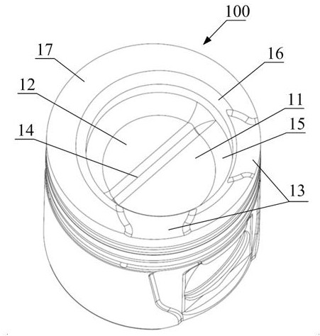
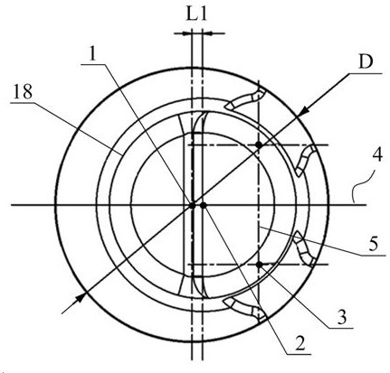
[0044] Please refer to Figure 2 to Figure 5 , figure 2 It is an oblique view of the overall structure of the piston in a specific embodiment of the present invention; image 3 It is a top view of the upper end of the piston in a specific embodiment of the present invention; Figure 4 It is a schematic diagram of the included angle between the step boundary direction line and the center line of the exhaust valve in the specific embodiment of the present inv...


PUM


Abstract

The invention discloses a combustion chamber which is used for a gas engine. The combustion chamber comprises a piston upper top face located at the top of a piston and a combustion chamber pit sunkendownwards relative to the piston upper top face, and the center line of the combustion chamber pit deviates by a preset distance towards one side of an exhaust valve relative to a piston center line.The combustion chamber pit comprises a first pit part located below the exhaust valve and a second pit part located below an intake valve, and the depth of the first pit part is larger than that of the second pit part. According to the scheme, tumble intensity can be enhanced in the compression process, tumble is violently broken into turbulent flow through a step-shaped structure at the bottom of the combustion chamber pit in the final stage of compression, vortexes close to the lower surface of the piston are also violently broken, and therefore the flame propagation speed is increased, andturbulent kinetic energy and heat efficiency are improved. According to the scheme, the combustion speed near the side of the exhaust valve can be increased through the eccentrically-arranged combustion chamber pit, and the knocking risk is reduced. The invention further discloses the gas engine.

Description

technical field [0001] The invention relates to the technical field of engines, in particular to a combustion chamber and a gas engine. Background technique [0002] At present, gas engines are generally modified on the basis of diesel engines. For diesel engines, the vortex generated by the swirling air passage helps to mix the oil jet and air to a certain extent, so as to achieve the goals of high-efficiency combustion and low pollutant emissions. The gas engine is mostly premixed combustion, which does not require high swirl strength. The fuel has been mixed with the air during the intake process, and after the spark plug is ignited to form a fire core, the ideal state is that there is high turbulent kinetic energy in the cylinder during the combustion process. The improvement of turbulent kinetic energy will accelerate the speed of flame propagation, which is of great significance for improving the combustion process of gas engines and reducing cycle fluctuations. If t...

Claims


Application Information

Patent Timeline
Patent Type & Authority Applications(China)
IPC IPC(8): F02B23/10F02F3/26F02B43/06F02B43/04
CPCF02B23/10F02B43/04F02B43/06F02B2023/106F02B2023/108F02F3/26Y02T10/12Y02T10/30
Inventor 李卫吕顺潘洁王慧
Owner WEICHAI POWER CO LTD
Why Eureka
Try Eureka