Prefabricated building partition wall structure based on BIM technology
A technology, partition wall technology, applied in the field of prefabricated building partition wall structure, to achieve the effect of simple operation, short construction period and easy replacement
- Summary
- Abstract
- Description
- Claims
- Application Information
AI Technical Summary
Problems solved by technology
Method used
Image
Examples
Embodiment 1
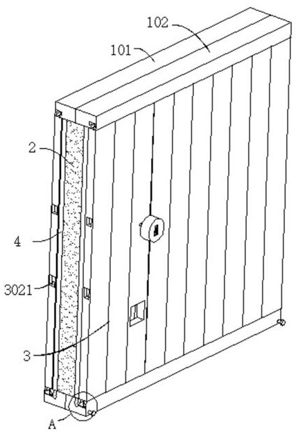
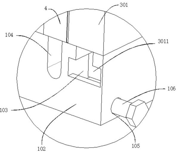
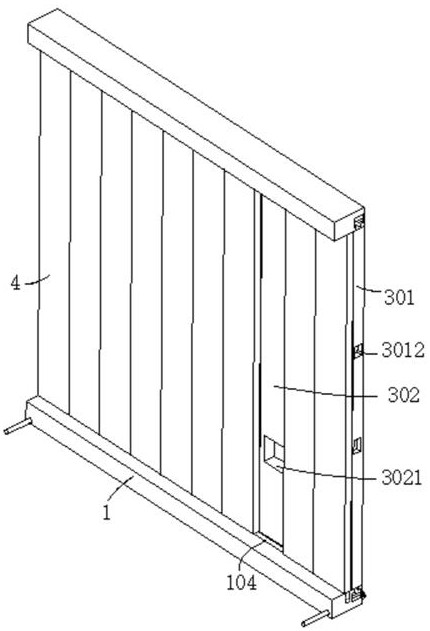
[0038] refer to Figure 1-8 , a prefabricated building partition wall structure based on BIM technology, including two fixing seats 1, a partition wall main body 2 and two decorative wall panels 3 are connected between the two fixing seats 1, and the two decorative wall panels 3 are respectively connected On the outer walls of both sides of the partition wall main body 2, the decorative wall panel 3 includes a first wall panel 301 and a second wall panel 302, the top and bottom of the first wall panel 301 are fixedly connected with a moving block 3011, and the outer wall of the fixed seat 1 is excavated with The moving groove 103 matched with the moving block 3011, the outer wall of the second wallboard 302 is dug with a socket groove 3021, the second wallboard 302 is provided with a positioning mechanism, and the outer wall of the first wallboard 301 is dug with a positioning groove matching the positioning mechanism 3012, the outer wall of the fixing seat 1 is dug with a pip...
Embodiment 2
[0043] refer to Figure 6-9 , a prefabricated building partition wall structure based on BIM technology, which is basically the same as that of Embodiment 1, furthermore, the outer wall of the knob 5 is dug with a first groove 503, and a pull block 5031 is movably connected in the first groove 503, The pull block 5031 is connected with the square rod 5032 through bearing rotation, and the movable groove 504 matched with the square rod 5032 is excavated in the knob 5, the first groove 503 communicates with the movable groove 504, and the outer wall of the square rod 5032 is sleeved with an elastic element 5033 , the two ends of the elastic element 5033 are respectively connected to the inner wall of the movable groove 504 and the outer wall of the pull block 5031 .
[0044] The square rod 5032 is slidably connected in the connecting pipe 501. The outer wall of the driving bevel gear 502 is dug with a movable hole 5021 matching with the square rod 5032, and the outer wall of the...
Embodiment 3
[0047] refer to figure 1 , figure 2 and Figure 10 , a prefabricated building partition wall structure based on BIM technology, which is basically the same as that of Embodiment 1, furthermore, the fixing base 1 includes a first fixing frame 101 and a second fixing frame 102, and the first fixing frame 101 and the second fixing frame The outer wall of the fixed frame 102 is dug with a matching threaded hole 105, and a fastening bolt 106 is movably connected in the threaded hole 105; by making the fastening bolt 106 fix the first fixed frame 101 and the second fixed frame 102, it is convenient to connect the wall structure. installation and disassembly.
[0048] The outer wall of the moving block 3011 is dug with a second groove 7, the inner wall of the second groove 7 is connected with a rotating shaft, and the outer wall of the rotating shaft is connected with a roller 701; during the moving process of the moving block 3011, the roller 701 slides in the moving groove 103, ...
PUM
 Abstract
Description
Claims
Application Information
 - R&D
- Intellectual Property
- Life Sciences
- Materials
- Tech Scout
- Unparalleled Data Quality
- Higher Quality Content
- 60% Fewer Hallucinations
Browse by: Latest US Patents, China's latest patents, Technical Efficacy Thesaurus, Application Domain, Technology Topic, Popular Technical Reports.
© 2025 PatSnap. All rights reserved.Legal|Privacy policy|Modern Slavery Act Transparency Statement|Sitemap|About US| Contact US: help@patsnap.com


