
Support foundation conversion structure in limited space and construction method

A technology for transforming structures and limited spaces. It is applied in the direction of basic structure engineering, buildings, sheet pile walls, etc. It can solve the problems of prolonging the construction period, interfering with the construction plan, and the influence of the walking route of mechanical equipment, so as to shorten the construction period and achieve stability and safety. The effect of supporting and improving the convenience of construction

Active Publication Date: 2021-01-08
CHINA CONSTR FIRST BUILDING GRP CORP LTD +1
View PDF6 Cites 0 Cited by
  • Summary
  • Abstract
  • Description
  • Claims
  • Application Information

AI Technical Summary

Problems solved by technology

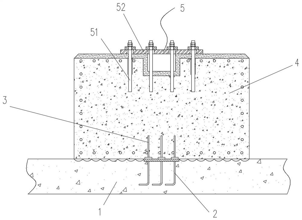
However, the foundation structure surface is poured first, and the indoor equipment is installed last. Various construction operations of the building body and auxiliary structures are required in the middle. If the method of reserving steel bars is used to solve the anchoring problem, the foundation structure surface will be laid As the construction progresses, during the construction process of the building body or the installation process of entertainment equipment, material transportation, assembly site, hoisting site, large crawler crane and other operations, due to the limited indoor space It will cause a great impact on the walking route of mechanical equipment, seriously interfere with the construction plan, and greatly prolong the construction period. The present invention provides a support foundation conversion structure and construction method in a limited space to achieve the above goals

Method used


Image

  • Support foundation conversion structure in limited space and construction method
  • Support foundation conversion structure in limited space and construction method
  • Support foundation conversion structure in limited space and construction method

Examples


Embodiment Construction

[0029]The technical solutions in the embodiments of the present invention will be clearly and completely described below in conjunction with the accompanying drawings of the specification. Obviously, the described embodiments are only a part of the embodiments of the present invention, rather than all the embodiments. Based on the embodiments of the present invention, all other embodiments obtained by those of ordinary skill in the art without creative work shall fall within the protection scope of the present invention.

[0030]In the description of this patent, it should be understood that the terms "center", "upper", "lower", "front", "rear", "left", "right", "vertical", "horizontal", The orientation or positional relationship indicated by "top", "bottom", "inner", "outer", etc. are based on the orientation or positional relationship shown in the drawings, and are only for the convenience of describing the patent and simplifying the description, rather than indicating or implying Th...


PUM


Abstract

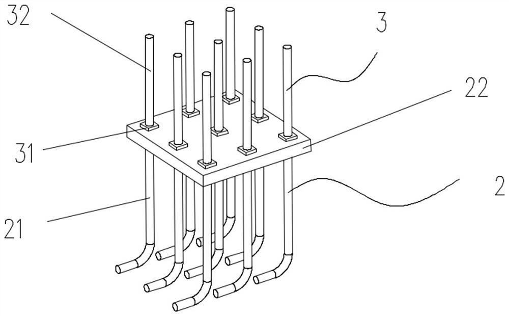
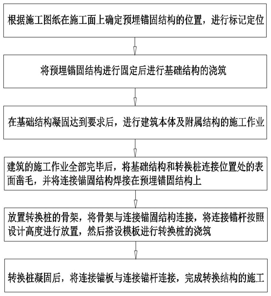
The invention discloses a support foundation conversion structure in limited space and a construction method. The support foundation conversion structure is used for being connected with a support column of equipment, and the conversion structure comprises a foundation structure, a pre-embedded anchoring structure, a connecting anchoring structure, a conversion pile and a connecting foundation. The pre-embedded anchoring structure is arranged in the foundation structure, the connecting anchoring structure is arranged in the conversion pile, the connecting anchoring structure is connected withthe pre-buried anchoring structure, the conversion pile is connected to the foundation structure, and the connecting foundation is arranged on the conversion pile and connected with the support columnof the equipment. Anchoring steel bars of the equipment are lifted in space, the anchoring steel bars are arranged in a delayed manner in time, the situation that the anchoring steel bars extending out of the ground influence the middle construction process is avoided, orderly construction is guaranteed, the construction convenience is effectively improved, and the construction period is effectively shortened.

Description

Technical field[0001]The invention relates to the technical field of building construction, in particular to a supporting base conversion structure in a limited space and a construction method.Background technique[0002]With the advancement of building construction technology, more single buildings with large-span spatial structures have appeared. As large single buildings are used as exhibition halls, shopping malls or indoor entertainment cities, various large-scale entertainment or commercial The demand for facilities is also increasing. Since entertainment equipment is generally directly erected on the surface of the indoor basic structure, and because most entertainment equipment is vibrating equipment with large bending moments, the foundation and structural slabs of entertainment equipment need to be reliably connected. In reinforced concrete structures The common method of connection is steel anchoring. However, the basic structure surface is the first to be poured, and the i...

Claims


Application Information

Patent Timeline
Patent Type & Authority Applications(China)
IPC IPC(8): E02D27/44E02D5/74E02D5/22
CPCE02D27/44E02D5/74E02D5/22
Inventor 张亮游滔陈松林赵永平殷丽曲志刚蒋丽娟杨君窦云城刘建业赵垒王新安
Owner CHINA CONSTR FIRST BUILDING GRP CORP LTD
Learn More