
Wire spool for carbon fiber wires

A carbon fiber wire and spool technology, which is applied in the field of electric equipment, can solve the problems that the cable usage is not large, the transportation is inconvenient, and the space is occupied.

Active Publication Date: 2021-01-08
国网河南省电力公司桐柏县供电公司
View PDF7 Cites 2 Cited by
  • Summary
  • Abstract
  • Description
  • Claims
  • Application Information

AI Technical Summary

Problems solved by technology

[0002] Carbon fiber wire is a new energy-saving capacity-enhancing wire with a new structure. Compared with conventional wires, it has light weight, high tensile strength, good heat resistance, small thermal expansion coefficient, small high-temperature sag, high conductivity, and low wire loss. , large carrying capacity, good corrosion resistance, not easy to icing, etc., comprehensively solve various technical bottlenecks in the field of overhead power transmission, represent the technical development trend of overhead conductors in the future, and contribute to the construction of safety, environmental protection and high efficiency The energy-saving transmission network has been widely used in the transformation of old lines. In the existing technology, most of the wires are wound on the winding reel, and then the winding reel is placed on the pay-off rack to release the wires. The wires on the winding reel Generally, only one kind of cable is wound in the slot. Because more than one kind of cable is placed in the cable, it is often necessary to prepare two or more winding reels. Some cables are not used in a large amount, so one is also carried The winding reel obviously takes up a lot of space and is inconvenient to transport
[0003] The Chinese utility model patent with the publication number CN 207108124 U discloses a cable winding reel, including a winding reel, which includes a main shaft and support parts arranged at both ends of the main shaft, and the opposite end surfaces of the winding reel Both ends of the main shaft are embedded with a first bearing, and the two ends of the main shaft are respectively installed in the bearing holes of the first bearing. More than one winding device is installed on the main shaft, and a coil is formed between two adjacent winding devices. The wire cavity and the winding device adjust the position left and right on the main shaft through the thread. This utility model divides a winding reel, and the wire can be unwound on the winding reel through the main shaft, and can be evenly spaced in the winding device and the winding chamber. Winding cables can realize the common winding of various cables. Each winding device has its own independent rotation direction, but each winding reel can only be manually rotated independently to take up the wires. It is troublesome to take up and pay off the wires.

Method used


Image

  • Wire spool for carbon fiber wires
  • Wire spool for carbon fiber wires
  • Wire spool for carbon fiber wires

Examples


Embodiment 1

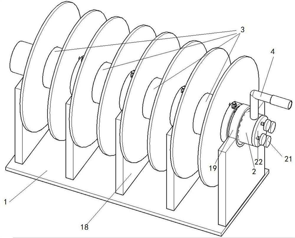
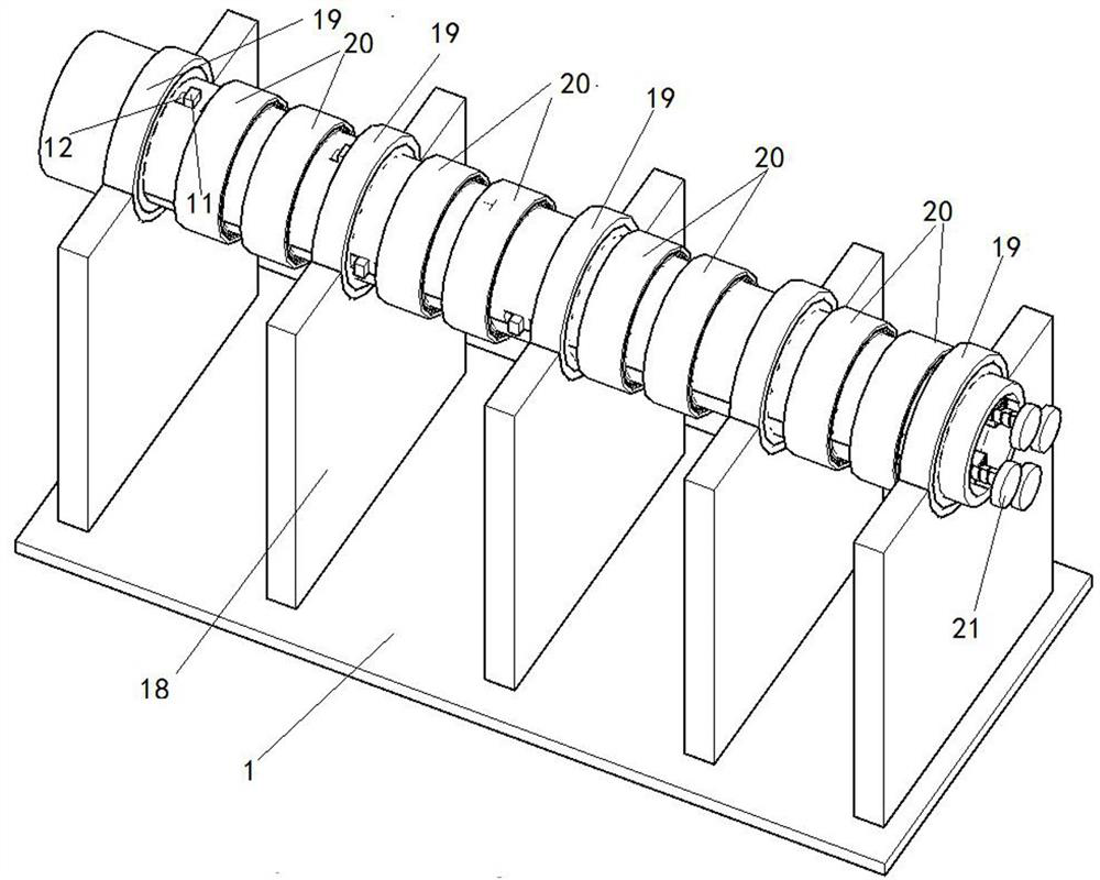
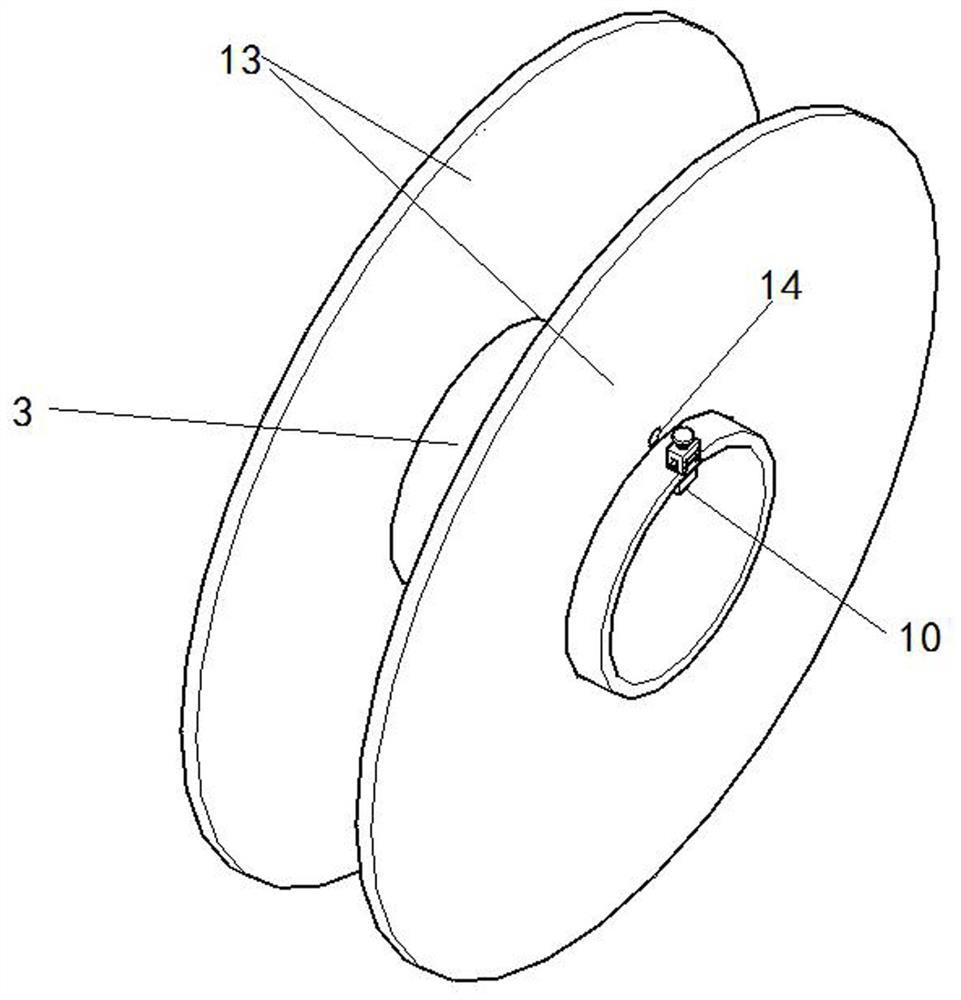
[0027] Such as Figure 1-7 Shown is the first embodiment of the present invention, a winding reel for carbon fiber wires, including a base 1, the base 1 is a cuboid plate-shaped structure, the base 1 is rotated and connected to the shaft 2, and the connection method is: vertical welding on the base 1 five risers 18, such as figure 1 with figure 2 As shown, the top of the vertical plate 18 is machined with an arc-shaped groove by a lathe, the inner shell of the arc-shaped groove is glued to the bearing one 19, and the shaft 2 is inserted into the bearing one 19 and fixed by glue. The four cylinders 3 are connected by rotation, and the connection method is: two bearings 20 are glued in the cylinder 3, and the bearings 20 are glued on the rotating shaft 21. At this time, the cylinders 3 can rotate freely on the rotating shaft 2, adjacent to each other. There is a vertical plate 18 between the cylinders 3, and the cylinder 3 is provided with a fixed component one for fixing the...

Embodiment 3

[0034] Such as Figure 9 Shown is the third embodiment of the present invention. The difference between this embodiment and Embodiment 1 is that universal brake wheels 16 are installed at the four corners of the bottom surface of the base 1, and the handle 2 17 is welded on the right side of the top surface of the base 1, so that the staff can move the base conveniently. 1. Increase the flexibility of use.


PUM


Abstract

The invention discloses a wire spool for carbon fiber wires, which comprises a base, a rotating shaft is rotatably connected to the base, a plurality of barrels are rotatably connected to the rotatingshaft, first fixing assemblies for fixing the starting ends of the carbon fiber wires are arranged on the barrels, and the rotating shaft is of a hollow structure; and a plurality of control assemblies for controlling the barrels and the rotating shaft to rotate synchronously are arranged in the rotating shaft, and a first handle is arranged at one end of the rotating shaft. According to the wirespool, the multiple carbon fiber wires can be wound, driving is achieved through a motor, manual wire winding is not needed, and wire unwinding operation can be conducted while wire winding is conducted.

Description

technical field [0001] The invention relates to the technical field of electric equipment, in particular to a winding reel for carbon fiber wires. Background technique [0002] Carbon fiber wire is a new energy-saving capacity-enhancing wire with a new structure. Compared with conventional wires, it has light weight, high tensile strength, good heat resistance, small thermal expansion coefficient, small high-temperature sag, high conductivity, and low wire loss. , large carrying capacity, good corrosion resistance, not easy to icing, etc., comprehensively solve various technical bottlenecks in the field of overhead power transmission, represent the technical development trend of overhead conductors in the future, and contribute to the construction of safety, environmental protection and high efficiency The energy-saving transmission network has been widely used in the transformation of old lines. In the existing technology, most of the wires are wound on the winding reel, an...

Claims


Application Information

Patent Timeline
IPC IPC(8): B65H75/38B65H75/44
CPCB65H75/38B65H75/44
Inventor 王金华钟雨王风华代立赟王珊珊
Owner 国网河南省电力公司桐柏县供电公司
Learn More