Human body temperature measuring system based on face recognition
A face recognition and measurement system technology, applied in the field of body temperature measurement, can solve problems such as the mismatch between body temperature data and users, achieve timely alarms for abnormal body temperatures, improve effectiveness and authenticity, and facilitate disassembly
- Summary
- Abstract
- Description
- Claims
- Application Information
AI Technical Summary
Problems solved by technology
Method used
Image
Examples
Embodiment 1
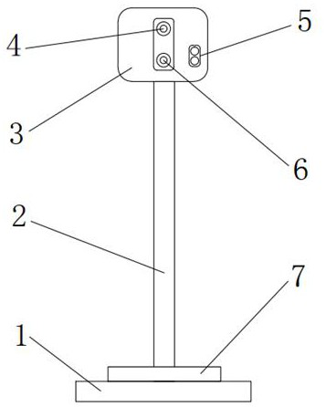
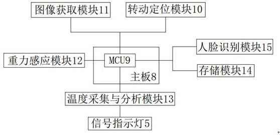
[0023] Embodiment one: refer to Figure 1-2, the technical solution adopted by the present invention is as follows: a human body temperature measurement system based on face recognition, comprising a base 1 and a support rod 2; the bottom of the support rod 2 is fixedly installed on the base 1; There is a gravity sensor 7; a control box 3 is fixedly installed on the top of the support rod 2; a main board 8 is arranged inside the control box 3; an MCU9 is arranged inside the main board 8; the gravity sensor 7 is fixedly installed on the bottom plate The gravity sensor 7 is provided with a gravity sensor module 12, and when the body temperature personnel to be detected stands on the gravity sensor 7, the gravity sensor module 12 senses the gravity of the detection personnel in the gravity sensor 7, and the gravity signal is delivered to the MCU9, After the MCU9 receives the signal, the temperature measuring device is started; the control box 3 is provided with a positioning came...
Embodiment 2
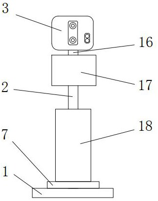
[0024] Embodiment two: refer to image 3 and Figure 4 The only difference between this embodiment and Embodiment 1 is that: the support rod is provided with a rotation mechanism, the rotation mechanism is fixedly installed on the top of the support rod, and the rotation mechanism includes a rotation mechanism housing 17, a micro motor 1705 and a first reducer 1703 , the micromotor 1705 and the first reducer 1703 are fixedly installed on the inner wall of the rotating mechanism housing 17, and one end of the micromotor 1705 and the first reducer 1703 is connected through the first output shaft 1704; the first reducer 1703 The other end is installed with a first rotating shaft 1701, and the other end of the first rotating shaft 1701 is installed below the first shaft sleeve 1702, and the first shaft sleeve 1702 is fixedly installed on the rotating mechanism housing 17; above the first shaft sleeve 1702 A rotating rod 16 is installed; the rotating rod 16 is fixedly connected to...
Embodiment 3
[0025] Embodiment three: refer to image 3 and Figure 5 The only difference between this embodiment and Embodiment 1 is that: a lifting mechanism is installed on the base; The plate 1813 divides the interior of the lifting mechanism housing into upper and lower machine compartments. The lower machine compartment is provided with a power mechanism, and the upper machine compartment is provided with a screw slider mechanism, wherein the upper machine compartment is a semi-closed machine compartment; The power mechanism includes a servo motor 1801 and a second reducer 1803, the servo motor 1801 and the second reducer 1803 are fixedly installed on the inner wall of the lower machine compartment, and the servo motor 1801 and the second reducer 1803 pass through the second output shaft 1802 connected, the other end of the second reducer 1803 is installed with a second rotating shaft 1804; the other end of the second rotating shaft 1804 is installed under the second bushing 1805, a...
PUM
 Abstract
Description
Claims
Application Information
 - R&D
- Intellectual Property
- Life Sciences
- Materials
- Tech Scout
- Unparalleled Data Quality
- Higher Quality Content
- 60% Fewer Hallucinations
Browse by: Latest US Patents, China's latest patents, Technical Efficacy Thesaurus, Application Domain, Technology Topic, Popular Technical Reports.
© 2025 PatSnap. All rights reserved.Legal|Privacy policy|Modern Slavery Act Transparency Statement|Sitemap|About US| Contact US: help@patsnap.com


