Heat dissipation structure, battery module, heat dissipation system and control method of heat dissipation system

A technology of heat dissipation structure and battery module, applied in the field of heat conduction, can solve the problem of poor heat dissipation effect at the connection row, and achieve the effect of improving heat dissipation efficiency

Pending Publication Date: 2021-01-05
ZHUHAI YINLONG ELECTRICAL APPLIANCES +1
View PDF0 Cites 0 Cited by
  • Summary
  • Abstract
  • Description
  • Claims
  • Application Information

AI Technical Summary

Problems solved by technology

[0005] The main purpose of the present invention is to provide a heat dissipation structure, a battery module, a heat dissipation system, and a control method for the heat dissipation system, so as to solve the problem of poor heat dissipation at the connecting row of the battery module in the prior art

Method used


Image

  • Heat dissipation structure, battery module, heat dissipation system and control method of heat dissipation system
  • Heat dissipation structure, battery module, heat dissipation system and control method of heat dissipation system
  • Heat dissipation structure, battery module, heat dissipation system and control method of heat dissipation system

Examples


Embodiment Construction

[0039] It should be noted that, in the case of no conflict, the embodiments in the present application and the features in the embodiments can be combined with each other. The present invention will be described in detail below with reference to the accompanying drawings and examples.

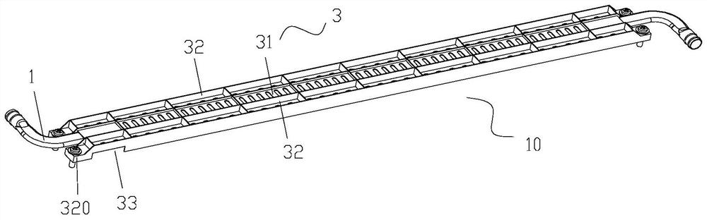
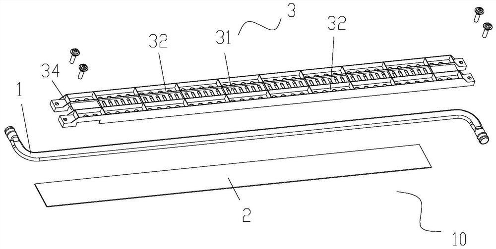
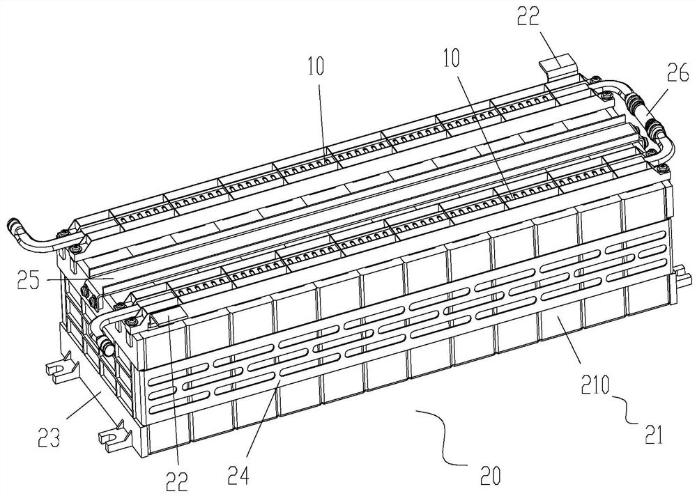
[0040] Such as figure 1 and Figure 7 As shown, the present invention provides a heat dissipation structure, including: a liquid cooling tube 1, the liquid cooling tube 1 is located on the side of the connecting row 22 of the battery module away from the cell assembly 21, and the extending direction of the liquid cooling tube 1 is parallel to the connection The extension direction of the row 22 is used to dissipate heat from the battery module by feeding the flowing cooling liquid into the liquid cooling tube 1; the insulating part 2, the insulating part 2 is strip-shaped, and the extending direction of the insulating part 2 is parallel to the liquid cooling tube 1 In the direction of extensi...


PUM


Abstract

The invention provides a heat dissipation structure, a battery module, a heat dissipation system and a control method of the heat dissipation system. The heat dissipation structure comprises a liquidcooling pipe, wherein the liquid cooling pipe is located at one side, far away from a battery cell assembly, of a connecting row of the battery module, and the extension direction of the liquid cooling pipe is parallel to the extension direction of the connecting row; flowing cooling liquid is introduced into the liquid cooling pipe to dissipate heat of the battery module; the insulating part is in a strip shape, the extending direction of the insulating part is parallel to the extending direction of the liquid cooling pipe, the insulating part is located between the liquid cooling pipe and the connecting bar so that the liquid cooling pipe and the connecting bar can be insulated, and the insulating part makes contact with the liquid cooling pipe and the connecting bar so that heat of theconnecting bar can be transmitted to the liquid cooling pipe. According to the heat dissipation structure provided by the invention, a problem of poor heat dissipation effect at the connecting row ofthe battery module in the prior art is solved.

Description

technical field [0001] The invention relates to the field of heat conduction, in particular to a heat dissipation structure, a battery module, a heat dissipation system and a control method for the heat dissipation system. Background technique [0002] A battery module is a combination that can provide electrical energy and is one of the secondary structures that make up a battery system. Existing battery modules include cells, metal frames and busbars, and battery modules do not integrate heat dissipation modules. Its heat dissipation function is realized by installing a liquid cold plate at the bottom of the battery box. The installed liquid cold plate needs to bear the weight of all battery modules. Therefore, the liquid cold plate is not only filled with a large amount of liquid medium, but also requires a certain strength, so The currently used liquid cold plate accounts for a large proportion of the cabinet. [0003] The pole of the lithium-ion battery is connected t...

Claims


Application Information

Patent Timeline
Patent Type & Authority Applications(China)
IPC IPC(8): H01M10/613H01M10/63H01M10/653H01M10/6556H01M10/6567
CPCH01M10/613H01M10/63H01M10/653H01M10/6556H01M10/6567Y02E60/10
Inventor 朱中槐曾德添荆振洋王翱吴超孙丰涛李永业
Owner ZHUHAI YINLONG ELECTRICAL APPLIANCES
Why Eureka
Try Eureka