
Computer-aided design method for heating coil of electrical tar precipitator

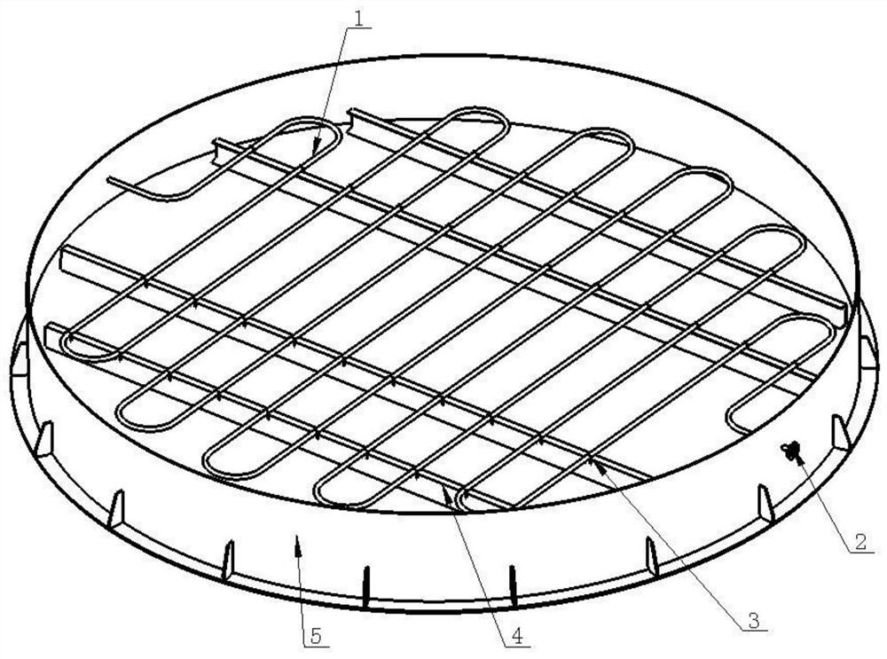
A computer-aided, electric tar catcher technology, applied in design optimization/simulation, special data processing applications, geometric CAD, etc., can solve the problems of low design efficiency, many operation steps, time-consuming and labor-intensive, etc., to achieve a wide range of applications, High degree of intelligence, avoiding the effect of reference disorder

Active Publication Date: 2021-01-05
XIANGYANG JIUDING HAOTIAN ENVIRONMENTAL PROTECTION EQUIP
View PDF4 Cites 0 Cited by
  • Summary
  • Abstract
  • Description
  • Claims
  • Application Information

AI Technical Summary

Problems solved by technology

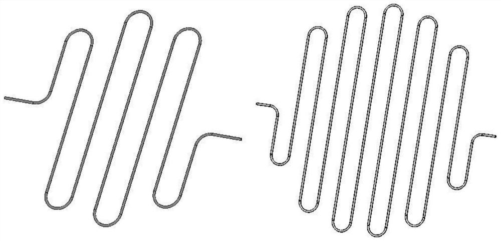
[0003]Because the electric tar catcher often needs to be customized according to the parameters provided by the customer, the structure of the heating coil of the electric tar catcher with different diameters is also different. Influenced by the difference in the structure of the tar catcher, the heating coils of the electric tar catcher with different diameters are difficult to reuse after modification of the model and drawings on the basis of previous projects, and it is often to rely on manual deduplication to start modeling and design, repetitive operations There are many steps, the design efficiency is low, and it is difficult to meet the urgent design schedule requirements
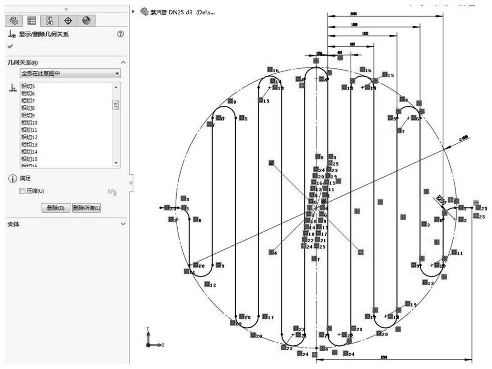
[0004]The difficulty in modeling the heating coil lies in the drawing of the scanning path of the heating pipe. The sketch outline uses a lot of commands such as arcs, tangent constraints, and dimensioning. After the model is completed, it needs to be imported into engineering drawings, marked with a large number of dimensions, and the path length of the entire heating pipe is manually calculated. The whole process is time-consuming and labor-intensive, and the efficiency is low.

Method used


Image

  • Computer-aided design method for heating coil of electrical tar precipitator
  • Computer-aided design method for heating coil of electrical tar precipitator
  • Computer-aided design method for heating coil of electrical tar precipitator

Examples


Embodiment Construction

[0031] The following will clearly and completely describe the technical solutions in the embodiments of the present invention with reference to the accompanying drawings in the embodiments of the present invention. Obviously, the described embodiments are only part of the embodiments of the present invention, not all of them. Based on the embodiments of the present invention, all other embodiments obtained by persons of ordinary skill in the art without making creative efforts belong to the protection scope of the present invention.

[0032] The invention provides a computer-aided design method for a heating coil of an electric tar catcher, which includes the following steps: (1) combing the design principles and material requirements in the design process of the heating coil, and finding out the difference between different project design processes; (2) According to the product parameters and characteristics obtained in step 1, design the main interface settings of the form to...


PUM


Abstract

The invention provides a computer-aided design method for a heating coil of an electrical tar precipitator, which comprises the following steps of: (1) carding design principles and material requirements in the design process of the heating coil, and finding out differences in the design process of different projects; (2) according to the product parameters and characteristics obtained in the step(1), window main interface setting is designed, so that the window main interface setting meets parameter input requirements of different projects; (3) compiling a program code by using a C# language, calling a corresponding function in the SolidWorks API to carry out secondary development on the program code, and debugging the compiled program, so that the compiled program can receive the inputof a user and correctly make a series of responses of modeling, assembling and engineering drawing; (4) verifying system operation conditions under different parameters, searching system vulnerabilities and repairing the system vulnerabilities in time; and (5) generating an installation package for the client to install and use. On the basis of a. Net development platform, customized development is carried out on the design work of the heating coil. Intelligent operation of automatic modeling, assembling and engineering drawing outputting of the heating coil is achieved.

Description

technical field [0001] The invention relates to the technical field of auxiliary design of heating coils, in particular to a computer-aided design method for heating coils of an electric tar catcher. Background technique [0002] The heating coil is a heating device with steam as the heat source. It is installed at the bottom of the electric tar catcher to heat the tar captured by the electric tar catcher to make it have better fluidity, so that the collected tar The tar is smoothly discharged through the tar outlet. [0003] Since the electric tar catcher often needs to be customized according to the parameters provided by the customer, the structure of the heating coil of the electric tar catcher with different diameters is also different. It is difficult to reuse the model and drawings after modification on the basis of previous projects, and the modeling and design are often started from the beginning with manual deduplication. There are many repetitive operation steps,...

Claims


Application Information

Patent Timeline
IPC IPC(8): G06F30/20G06F30/12G06F30/17
CPCG06F30/20G06F30/12G06F30/17
Inventor 吕洲王美华时扬邓迁君
Owner XIANGYANG JIUDING HAOTIAN ENVIRONMENTAL PROTECTION EQUIP
Learn More